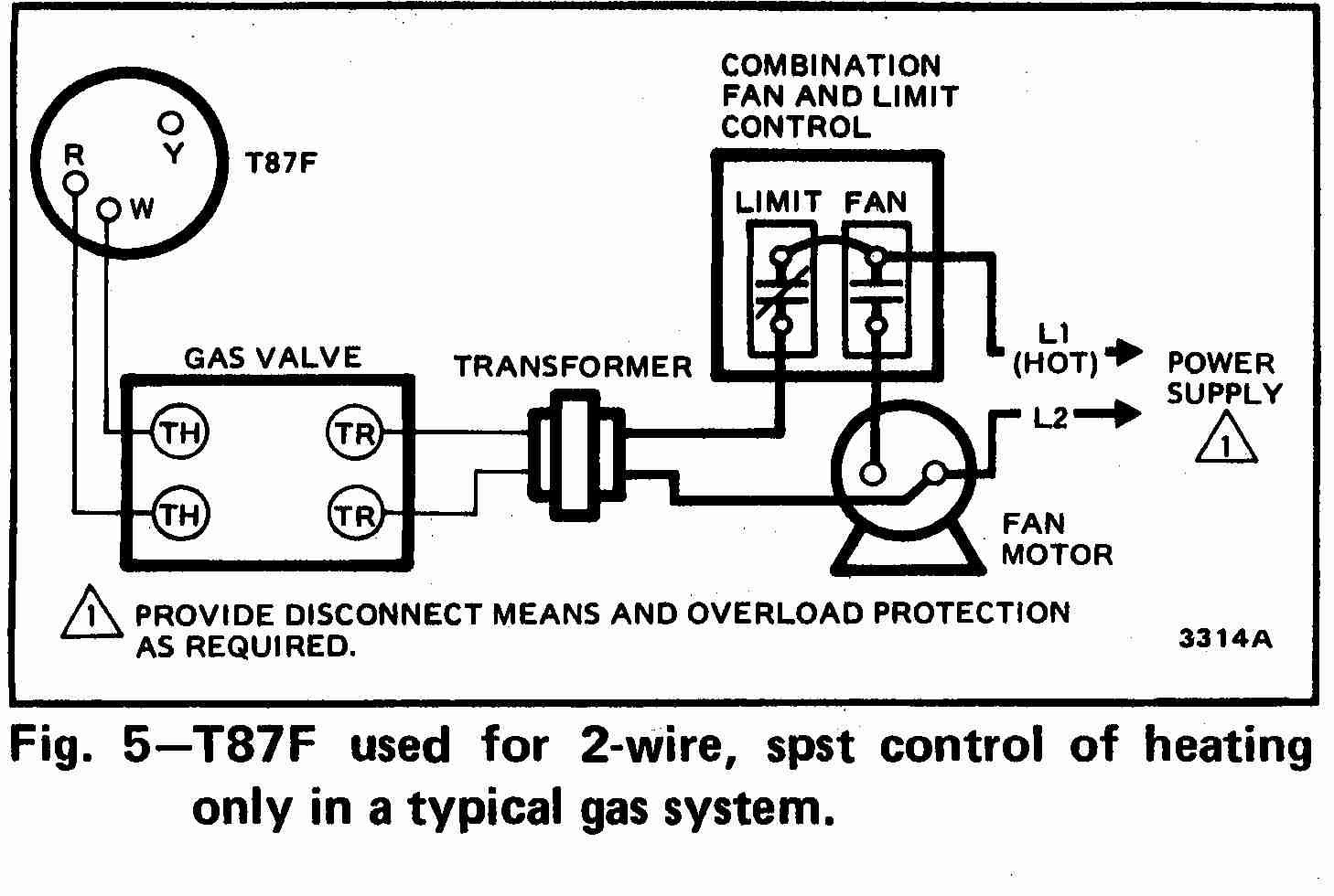
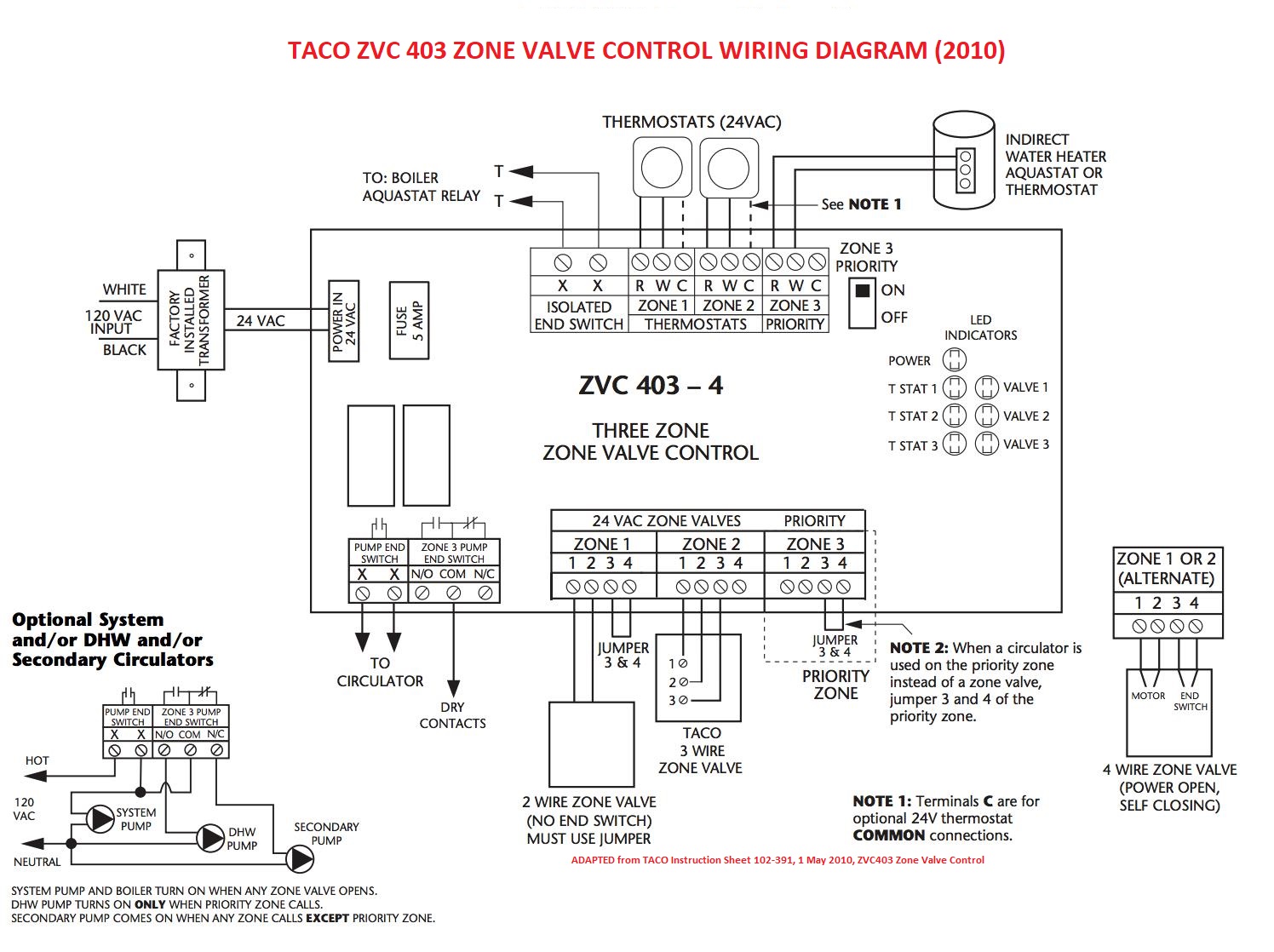
Zone Valve Wiring Diagram is a crucial tool for understanding the electrical connections within a zone valve system. It provides a visual representation of how the various components are connected and helps to troubleshoot any issues that may arise.
Why Zone Valve Wiring Diagrams are Essential
Zone Valve Wiring Diagrams are essential for the following reasons:
- Help to understand the electrical connections within a zone valve system
- Aid in troubleshooting any electrical issues that may occur
- Ensure proper installation and maintenance of the system
How to Read and Interpret Zone Valve Wiring Diagrams
Reading and interpreting Zone Valve Wiring Diagrams can seem daunting at first, but with a little guidance, it becomes much easier. Here are some tips:
- Identify the components and their corresponding symbols
- Follow the lines to see how the components are connected
- Pay attention to the labeling and color-coding of the wires
Using Zone Valve Wiring Diagrams for Troubleshooting
When faced with electrical problems in a zone valve system, referring to the Wiring Diagram can be incredibly helpful. Here’s how to use it for troubleshooting:
- Identify the problem area on the diagram
- Check for any loose connections or damaged wires
- Compare the diagram to the actual wiring to see if there are any discrepancies
Importance of Safety
Working with electrical systems can be dangerous, so it’s important to prioritize safety at all times. Here are some safety tips to keep in mind:
- Always turn off the power before working on any electrical components
- Use insulated tools to avoid electrical shocks
- Wear appropriate protective gear, such as gloves and goggles
- Consult a professional if you are unsure about any aspect of the wiring diagram
Zone Valve Wiring Diagram
Honeywell V8043e Zone Valve Wiring Diagram – IOT Wiring Diagram

Honeywell V8043 Zone Valve Wiring Diagram – Wiring Diagram

Honeywell 5 Wire Zone Valve Wiring Diagram: All You Need To Know

Zone Valve Wiring Installation & Instructions: Guide to heating system

hvac – Honeywell 5-wire zone valve wiring – Home Improvement Stack Exchange

💥 Boiler Zone Valve Wiring Diagram 👈

Zone Valve Wiring Manuals Installation & Instructions: Guide to heating

Zone Valve Wiring Installation & Instructions: Guide to heating system
