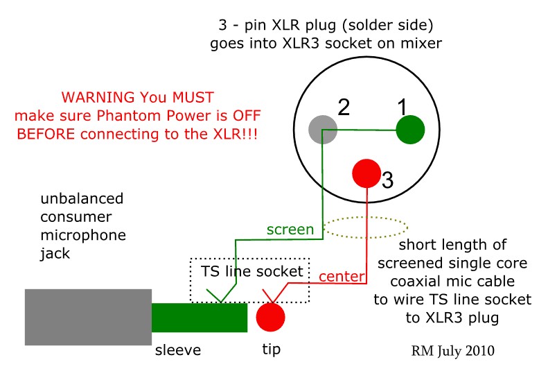
When it comes to understanding the intricacies of electrical systems, having a clear grasp of Xlr Connector Wiring Diagram is essential. These diagrams provide a visual representation of the connections within an XLR connector, helping technicians and enthusiasts alike to troubleshoot and optimize their setups effectively.
Importance of Xlr Connector Wiring Diagram
Xlr Connector Wiring Diagram are crucial for several reasons:
- Ensure proper connections between devices
- Identify potential issues or conflicts in the wiring
- Enable accurate repairs and modifications
Reading and Interpreting Xlr Connector Wiring Diagram
Reading an Xlr Connector Wiring Diagram can be daunting at first, but with practice, it becomes second nature. Here are some tips to help you interpret these diagrams effectively:
- Understand the symbols used in the diagram
- Follow the flow of connections from one component to another
- Pay attention to the color-coding of wires
Using Xlr Connector Wiring Diagram for Troubleshooting
Xlr Connector Wiring Diagram are invaluable when it comes to troubleshooting electrical problems. By referring to the diagram, you can:
- Identify the source of a malfunction
- Pinpoint where a connection has gone wrong
- Test specific components for faults
Safety Tips for Working with Xlr Connector Wiring Diagram
Working with electrical systems can be hazardous, so it’s crucial to prioritize safety at all times. Here are some safety tips and best practices to keep in mind:
- Always disconnect power sources before working on wiring
- Use insulated tools to prevent electrical shocks
- Double-check connections before powering up the system
Xlr Connector Wiring Diagram
Patrice Benoit Art: [27+] Port Wiring Diagram Xlr Y, What Is An XLR
![Xlr Connector Wiring Diagram Patrice Benoit Art: [27+] Port Wiring Diagram Xlr Y, What Is An XLR](https://i1.wp.com/i.pinimg.com/originals/45/b8/9d/45b89da1c6346307aa8085ef6465a90c.jpg)
Stereo Xlr Wiring
Standard Xlr Wiring Diagram Yamaha

Stereo Xlr Wiring Diagram – Wiring Diagram

How to Wire an XLR to a 1/4" TRS (Stereo Jack Plug)

XLR Connector Pinout

⭐Wiring Diagram Xlr⭐ – Fuelcell oakley grandsale

Mini Xlr Connector Wiring Diagram – canvas-depot
