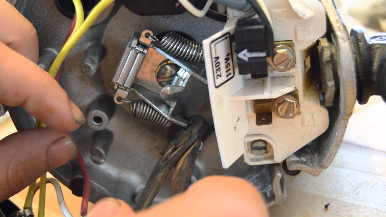
Are you looking to understand the intricacies of your pool pump timer’s wiring diagram? Wiring diagrams for pool pump timers are essential tools for anyone looking to install, maintain, or troubleshoot their pool pump system. By understanding how to read and interpret these diagrams, you can ensure that your pool pump operates efficiently and safely.
Why Wiring Diagrams For Pool Pump Timers Are Essential
- Helps in understanding the electrical connections of the pump timer
- Aids in troubleshooting electrical issues
- Ensures proper installation and maintenance of the pool pump system
Reading and Interpreting Wiring Diagram For Pool Pump Timer
When looking at a wiring diagram for a pool pump timer, it’s important to understand the different symbols and connections present. Here are some key points to keep in mind:
- Identify the different components of the timer such as the motor, power source, and control panel
- Understand the flow of electricity through the system and how each component is connected
- Follow the color-coding of wires to ensure proper connections
Using Wiring Diagram For Pool Pump Timer For Troubleshooting
Wiring diagrams for pool pump timers can be invaluable when it comes to troubleshooting electrical problems. By following the diagram and tracing the flow of electricity, you can pinpoint issues such as faulty connections, damaged wires, or malfunctioning components. This can help you fix the problem quickly and efficiently.
Importance of Safety
Working with electrical systems can be dangerous, so it’s important to prioritize safety when using wiring diagrams for pool pump timers. Here are some safety tips to keep in mind:
- Always turn off the power source before working on the pool pump system
- Use insulated tools to avoid electrical shocks
- Avoid working in wet conditions to prevent accidents
- If you’re unsure about a particular wiring connection, consult a professional electrician
Wiring Diagram For Pool Pump Timer
Intermatic Pool Timer Wiring Diagram Load Management

Grasslin Pool Timer Wiring Diagram – Wiring Diagram
Understanding 120V Intermatic Timer Wiring Diagrams – Wiring Diagram

Intermatic Timer Wiring Diagram – Doearth

115v Pool Pump Timer Wiring Diagram – inspireque

intermatic wiring diagram

Grasslin Timer Wiring Diagram Free Download | Manual E-Books

Pentair Pool Pump Wiring Diagram – coginspire
