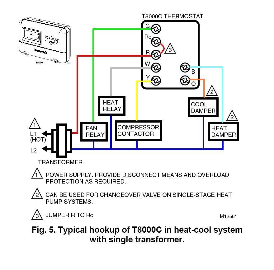
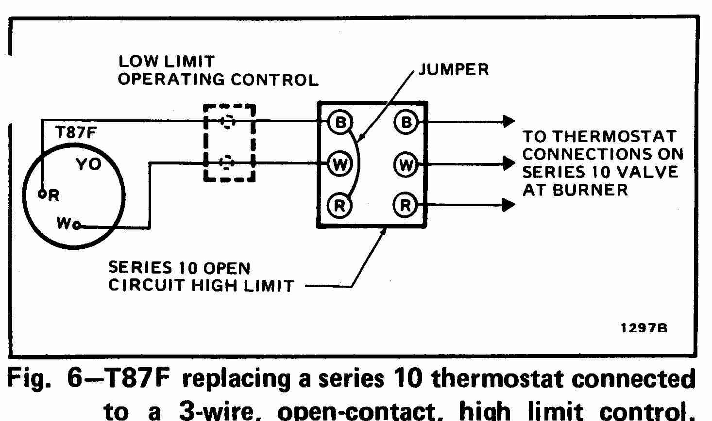
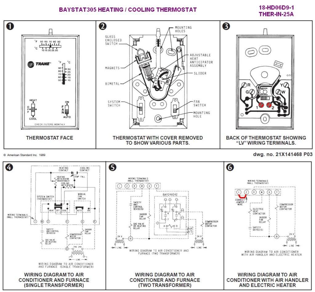
Are you looking to install or troubleshoot a Honeywell thermostat in your home? Understanding the wiring diagram for a Honeywell thermostat is crucial for ensuring that the installation is done correctly and for troubleshooting any electrical issues that may arise. Let’s delve into the details of how to interpret and use a wiring diagram for a Honeywell thermostat.
Why Wiring Diagrams for a Honeywell Thermostat are Essential
- Helps in correctly connecting wires to the thermostat
- Aids in identifying the function of each wire
- Ensures proper communication between the thermostat and HVAC system
Reading and Interpreting Wiring Diagrams for a Honeywell Thermostat
When looking at a wiring diagram for a Honeywell thermostat, it’s important to understand the symbols and color codes used. Here are some key points to keep in mind:
- Identify the terminals on the thermostat and the corresponding labels
- Match the wires from your HVAC system to the correct terminals on the thermostat
- Follow the wiring diagram carefully to prevent any electrical issues
Using Wiring Diagrams for Troubleshooting Electrical Problems
Wiring diagrams for a Honeywell thermostat can be invaluable when troubleshooting electrical problems. By following the diagram and checking the connections, you can quickly identify any issues and make the necessary repairs. Here are some tips for using the wiring diagram for troubleshooting:
- Check for loose or disconnected wires
- Verify that the wires are connected to the correct terminals
- Use a multimeter to test for continuity and voltage
Importance of Safety
When working with electrical systems and using wiring diagrams, safety should always be a top priority. Here are some safety tips and best practices to keep in mind:
- Always turn off the power before handling any electrical components
- Avoid touching live wires and terminals without proper protection
- Double-check all connections before restoring power
Wiring Diagram For A Honeywell Thermostat
Honeywell Ct87n4450 Thermostat Wiring Diagram

Heat Pump: Honeywell Heat Pump Thermostat Wiring Diagram

Honeywell Thermostat Rth111b Wiring Diagram

Wiring Honeywell Thermostat Instructions

Honeywell Thermostat Rth2300b

Wiring A Honeywell Thermostat With 4 Wires

Honeywell Thermostat Rth221b1000 Wiring Diagram – Wiring Diagram

Honeywell Rth6360 Wiring Diagram
