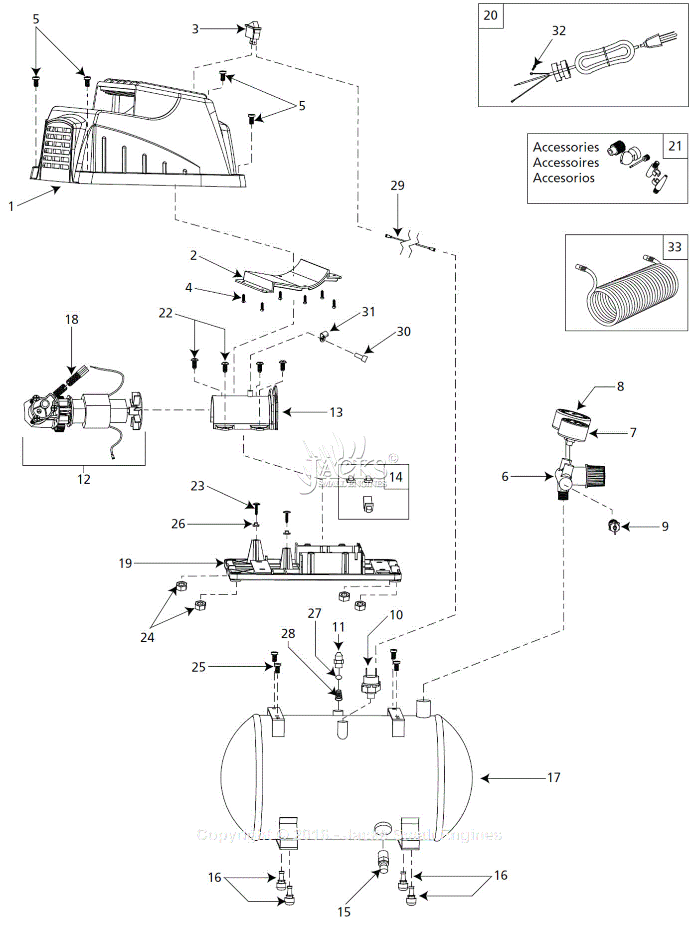
When it comes to understanding the electrical components of a compressor, a Wiring Diagram Compressor is an essential tool. This diagram provides a visual representation of the electrical wiring and connections within the compressor, helping mechanics and technicians troubleshoot electrical issues efficiently.
Why Wiring Diagram Compressor are essential
- Helps identify electrical components and connections
- Aids in troubleshooting electrical problems
- Ensures proper installation and maintenance
- Improves safety by understanding electrical circuits
Reading and Interpreting Wiring Diagram Compressor
Understanding how to read and interpret a Wiring Diagram Compressor is crucial for effectively troubleshooting electrical issues. Here are some key points to consider:
- Identify the key components and connections shown in the diagram
- Follow the flow of electrical current through the compressor
- Pay attention to symbols and color codes used in the diagram
- Refer to the legend or key for any unfamiliar symbols or abbreviations
Using Wiring Diagram Compressor for troubleshooting
Wiring Diagram Compressor are invaluable tools for diagnosing and resolving electrical problems in compressors. Here’s how they can be used effectively:
- Locate the specific component or connection causing the issue
- Check for continuity and proper voltage levels at different points in the circuit
- Trace the wiring to identify any loose connections or damaged wires
- Refer to the diagram to ensure correct reassembly after repairs
When working with electrical systems and using Wiring Diagram Compressor, safety should always be a top priority. Here are some important safety tips and best practices to keep in mind:
- Always turn off the power supply before working on electrical components
- Use insulated tools to prevent electric shock
- Avoid working on energized circuits whenever possible
- Double-check connections and wiring before powering up the compressor
- Seek professional help if unsure about any electrical work
Wiring Diagram Compressor
Compressor Wiring Diagram – Worksic

Copeland Hermetic Compressor Wiring Diagram – Wiring Diagram

How to make air compressor wiring diagram 3 phase | portable air

Embraco Compressor Wiring Diagram – Cadician's Blog

Campbell Hausfeld Air Compressor Motor Wiring Diagram

Wiring Diagram For Ac Compressor

Air Conditioner Compressor Wiring

Awesome Atlas Copco Compressor Wiring Diagram A 4 Way Light Switch
