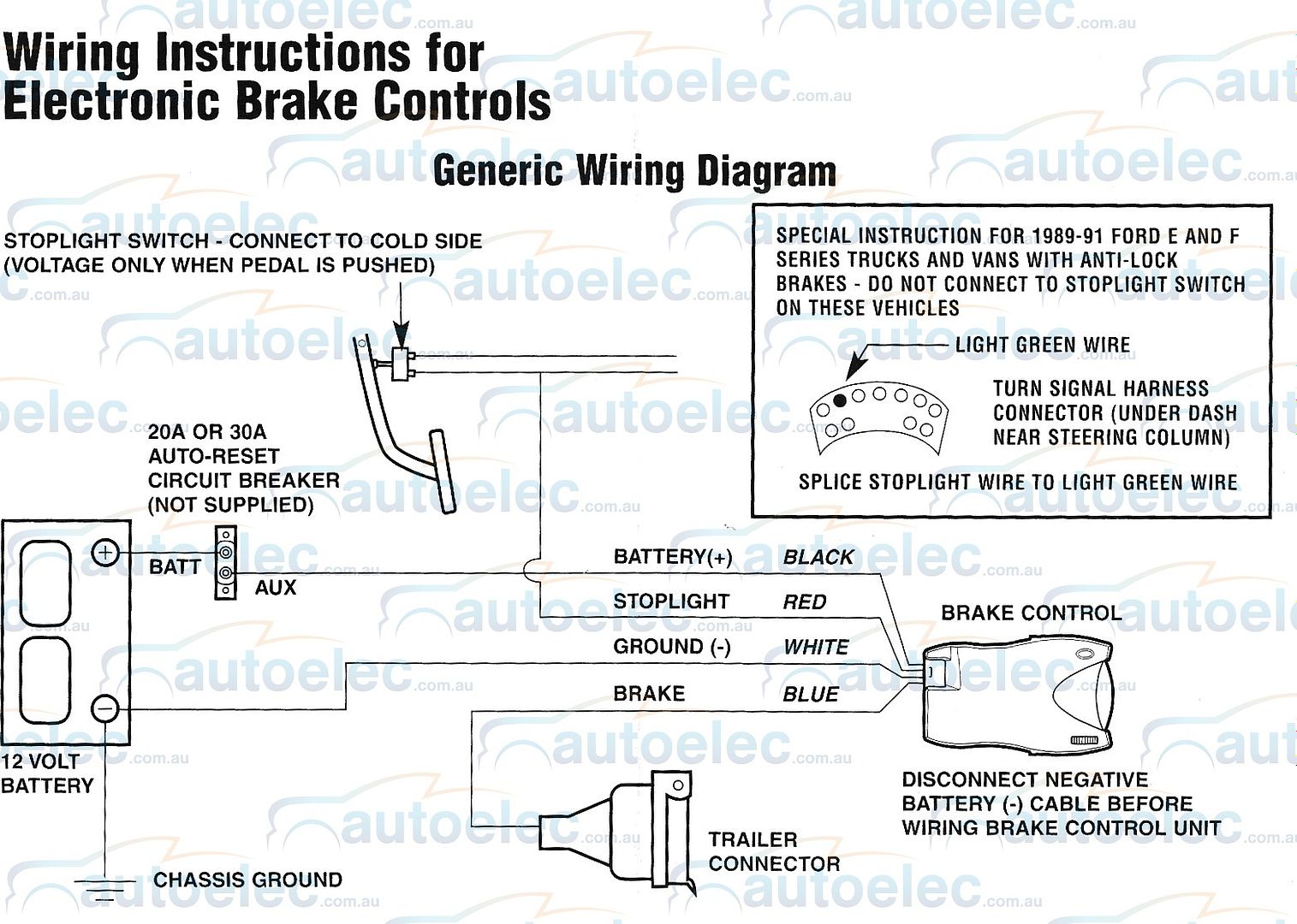
When it comes to ensuring the safety and efficiency of your vehicle’s braking system, having a Wiring Diagram Brake Controller is essential. This diagram provides a detailed illustration of the electrical connections and components involved in controlling the brakes, allowing you to troubleshoot issues and make necessary repairs.
Why Wiring Diagram Brake Controller are Essential
Wiring Diagram Brake Controller are crucial for several reasons:
- They provide a visual representation of the electrical connections in the brake controller system.
- Help in identifying the components involved in controlling the brakes.
- Allow for easier troubleshooting of electrical issues.
Reading and Interpreting Wiring Diagram Brake Controller
When reading a Wiring Diagram Brake Controller, it’s important to:
- Understand the symbols and colors used in the diagram.
- Follow the flow of the wiring from one component to another.
- Identify the connections and their corresponding functions.
Using Wiring Diagram Brake Controller for Troubleshooting
Wiring Diagram Brake Controller are invaluable when it comes to troubleshooting electrical problems in the brake system. They help in:
- Locating faulty connections or components.
- Testing the continuity of wires and connections.
- Verifying the proper functioning of the brake controller system.
Importance of Safety
When working with electrical systems and using Wiring Diagram Brake Controller, safety should always be a top priority. Here are some safety tips and best practices to follow:
- Always disconnect the battery before working on electrical components.
- Use insulated tools to prevent electrical shocks.
- Avoid working on electrical components in wet or damp conditions.
- Refer to the vehicle’s service manual for specific safety precautions.
Wiring Diagram Brake Controller
Wiring Diagram Brake Controller – Home Wiring Diagram

Tekonsha P3 Prodigy Electric Trailer Brake Controller Wiring Diagram

Electric Brake Controller Complete with Leader Cable to Wire to Trailer

Jean Scheme: Tekonsha P3 Brake Controller Wiring Diagram

Wiring Diagram Brake Controller – Home Wiring Diagram

Primus Electric Brake Controller Wiring Diagram

Curt Venturer Brake Controller Wiring Diagram

Ford Trailer Brake Controller Wiring Diagram
