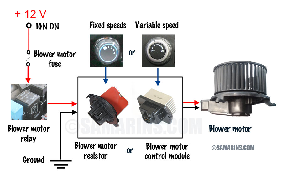
When working on a vehicle’s HVAC system, understanding the wiring diagram blower motor is crucial. The blower motor is responsible for pushing air through the vents, providing heating or cooling to the interior of the vehicle. By referencing the wiring diagram blower motor, mechanics can troubleshoot any electrical issues that may arise, ensuring the system operates efficiently.
Why are Wiring Diagram Blower Motor essential?
- Helps identify the different components of the blower motor system
- Guides the mechanic on how the system is wired and connected
- Aids in diagnosing electrical problems quickly and accurately
- Ensures proper installation and maintenance of the blower motor
How to read and interpret Wiring Diagram Blower Motor
When looking at a wiring diagram blower motor, it’s important to understand the symbols and color codes used. Each wire color represents a specific function, such as power, ground, or signal. Additionally, the diagram will show the connections between the blower motor, relay, resistor, and HVAC control module.
How Wiring Diagram Blower Motor are used for troubleshooting electrical problems
- Identify the source of the issue by following the wiring diagram
- Check for continuity and voltage at different points in the system
- Verify proper grounding and connections
- Test components such as the relay, resistor, and blower motor for functionality
Safety Tips when working with Wiring Diagram Blower Motor
- Always disconnect the battery before working on any electrical components
- Use insulated tools to prevent electric shock
- Avoid working on the system in wet conditions
- Double-check all connections before powering the system back on
Wiring Diagram Blower Motor
Sentra Blower Motor Wiring Diagram – Diagramming Tale

Understanding The 4 Speed Blower Motor Wiring Diagram – Moo Wiring

Ac Blower Motor Wiring Diagram – feb5-hangingoutbookmarkguide
⭐ Chevy Silverado 1500 Blower Motor Wiring Diagram ⭐

Wiring Diagram For Blower Motor

Blower Motor Wiring Diagram Manual

Wiring A Blower Motor

Chevy Blower Motor Resistor Wiring Diagram
