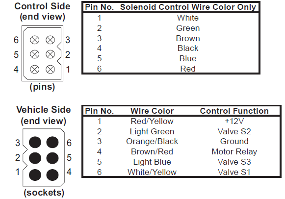
When it comes to understanding how to wire up a Western 6 Pin Controller, having access to a detailed wiring diagram is essential. The Western 6 Pin Controller Wiring Diagram provides a visual representation of the electrical connections and functions of the controller, making it easier to install, troubleshoot, and repair.
Why Western 6 Pin Controller Wiring Diagrams are Essential
- Ensure proper installation of the controller
- Aid in troubleshooting electrical issues
- Help in understanding the functionality of different components
- Reduce the risk of electrical hazards
How to Read and Interpret Western 6 Pin Controller Wiring Diagram
When looking at a Western 6 Pin Controller Wiring Diagram, it is important to understand the symbols and color codes used in the diagram. Each wire and connection is labeled with specific symbols and colors to indicate its function and location. By familiarizing yourself with these symbols, you can easily follow the wiring diagram and make the necessary connections.
Using Western 6 Pin Controller Wiring Diagram for Troubleshooting
When facing electrical problems with your Western 6 Pin Controller, referring to the wiring diagram can help pinpoint the issue. By tracing the electrical connections and checking for continuity, you can identify any faulty wires, connections, or components that may be causing the problem. This can save you time and effort in diagnosing and repairing the issue.
Importance of Safety
Working with electrical systems can be dangerous if proper precautions are not taken. When using wiring diagrams to install or troubleshoot a Western 6 Pin Controller, it is important to follow these safety tips:
- Always shut off power before working on electrical systems
- Use insulated tools to prevent electrical shock
- Double-check connections before powering up the system
- Wear appropriate safety gear, such as gloves and goggles
Western 6 Pin Controller Wiring Diagram
Western Plow Controller 6-pin Wiring Diagram

37+ Western 6 Pin Controller Wiring Diagram – ConnorRamin

Western 6 Pin Controller Wiring Diagram

37+ Western 6 Pin Controller Wiring Diagram – ConnorRamin

Western Plow Controller 6-pin Wiring Diagram Plow Unimount Hts Mvp

Western 6 Pin Controller Wiring Diagram
Understanding The Western 6 Pin Controller Wiring Diagram – Moo Wiring
Suburbanite (Personal Snowplow) Diagrams – Straight Blade Snowplow
