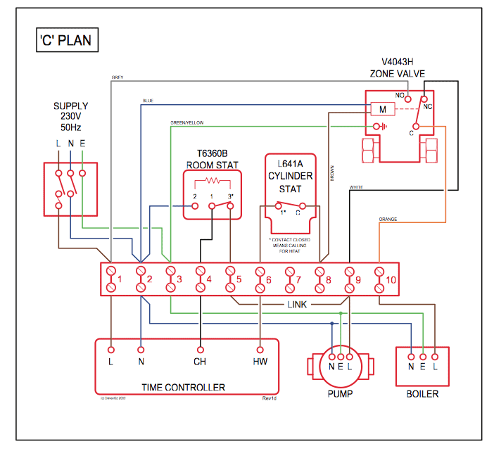
Are you looking to install a Viper remote starter in your vehicle but unsure how to navigate the wiring diagram? Understanding the Viper Remote Starter Wiring Diagram is crucial to ensure a successful installation and proper functioning of your remote starter system.
Why Viper Remote Starter Wiring Diagram is Essential
The Viper Remote Starter Wiring Diagram provides a detailed blueprint of the electrical connections and components involved in the installation of your remote starter system. It serves as a guide for technicians and DIY enthusiasts to properly wire the remote starter and avoid any potential electrical issues.
Reading and Interpreting Viper Remote Starter Wiring Diagram
When reading a Viper Remote Starter Wiring Diagram, it’s important to pay attention to the color codes, symbols, and labels used to represent different components and connections. Refer to the key or legend provided in the diagram to understand the meaning of each element.
Using Viper Remote Starter Wiring Diagram for Troubleshooting
Viper Remote Starter Wiring Diagrams are invaluable tools for troubleshooting electrical problems in your remote starter system. By following the wiring diagram and tracing the connections, you can identify any faulty components, loose connections, or incorrect wiring that may be causing issues with your remote starter.
Importance of Safety
- Always disconnect the vehicle’s battery before working on any electrical components.
- Use insulated tools to avoid the risk of electric shock.
- Avoid working on electrical systems in wet or damp conditions.
- If you are unsure about any electrical connections, seek professional help.
By familiarizing yourself with the Viper Remote Starter Wiring Diagram and following safety precautions, you can install and troubleshoot your remote starter system with confidence and peace of mind.
Viper Remote Starter Wiring Diagram
5×06 Viper Remote Start Wiring Diagram

Viper 5305v Remote Start Wiring Diagram

Viper 5101 Remote Start Wiring Diagram

Viper 5704Z Remote Start System | Crutchfield Video – YouTube

4105 Viper Remote Start Wiring Diagrams

Understanding The Viper Remote Starter Wiring Diagram – Wiring Diagram

Viper Remote Starter Wiring Diagram
