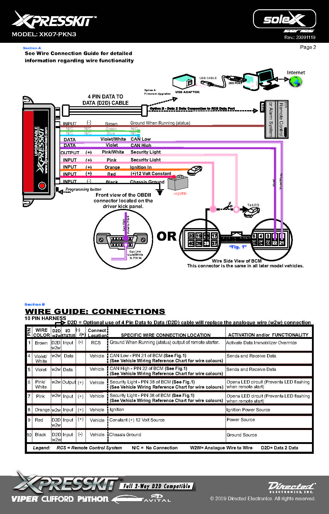
Viper Remote Start Wiring Diagram
When it comes to installing a Viper remote start system in your vehicle, understanding the wiring diagram is crucial for a successful installation. The Viper remote start wiring diagram provides a detailed overview of the electrical connections needed to integrate the remote start system with your vehicle’s existing wiring. By following the diagram accurately, you can ensure that the remote start system functions properly and that all connections are secure.
Why Viper Remote Start Wiring Diagrams are Essential
- Ensure proper installation of the remote start system
- Identify the correct wires for connecting the system to your vehicle
- Prevent potential electrical issues or damage
- Maximize the efficiency and performance of the remote start system
How to Read and Interpret Viper Remote Start Wiring Diagrams
- Identify key components such as relays, switches, and connectors
- Understand the color-coding of wires for easy identification
- Follow the flow of electrical connections from the remote start module to the vehicle’s wiring
- Refer to the legend or key for additional information on symbols and abbreviations
Using Viper Remote Start Wiring Diagrams for Troubleshooting
- Identify potential wiring issues or faulty connections
- Trace the flow of electrical signals to pinpoint the source of a problem
- Check for continuity and proper voltage levels at key points in the wiring diagram
- Refer to the troubleshooting guide for common issues and solutions
When working with Viper remote start wiring diagrams or any electrical systems, safety should always be a top priority. Here are some important safety tips to keep in mind:
- Disconnect the vehicle’s battery before working on any electrical components
- Use insulated tools to prevent electrical shock
- Avoid working on wiring in wet or damp conditions
- Double-check all connections before reapplying power to the system
- If you are unsure about any aspect of the installation, consult a professional technician
Viper Remote Start Wiring Diagram
Installing a Viper alarm/remote start, need a bit of help with the

Viper Remote Starter Wiring Diagram Professional Viper Remote Start

Viper Remote Starter Wiring Diagram 1000

How to Install a Viper 5704 Alarm/ Remote Start | Page 2 | Tacoma World
Viper 3606v Wiring Diagram

Wiring Diagram For Viper Remote Start – Wiring Digital and Schematic

Viper Car Starter Wiring Diagram

Viper 4105v Wiring Diagram – Wiring Diagram
