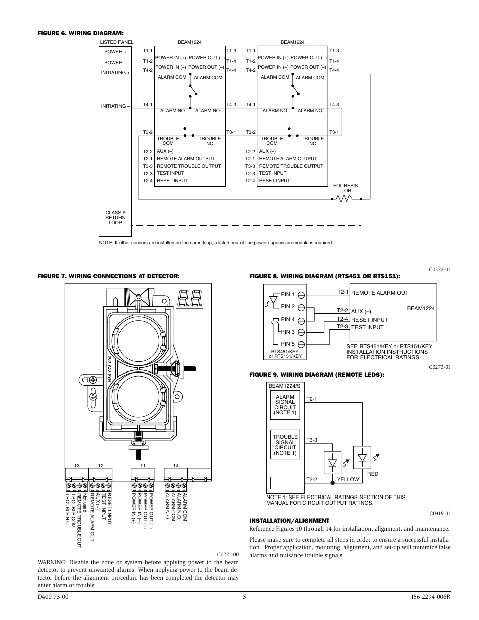
System Sensor Duct Detector Wiring Diagrams are crucial tools for understanding and implementing the electrical connections within duct detectors. These diagrams provide a visual representation of the wiring setup, helping technicians install, troubleshoot, and maintain the detectors effectively. By following the wiring diagram accurately, you can ensure the proper functioning of the system.
Why are System Sensor Duct Detector Wiring Diagrams Essential?
System Sensor Duct Detector Wiring Diagrams are essential for the following reasons:
- Ensure proper installation of the duct detector
- Aid in troubleshooting electrical issues
- Facilitate maintenance and repairs
- Improve overall system reliability
How to Read and Interpret System Sensor Duct Detector Wiring Diagrams
When interpreting System Sensor Duct Detector Wiring Diagrams, follow these steps:
- Start by identifying the components labeled in the diagram
- Understand the connections between different components
- Follow the wiring paths to ensure correct installation
- Refer to the legend or key for any symbols used in the diagram
Using System Sensor Duct Detector Wiring Diagrams for Troubleshooting
System Sensor Duct Detector Wiring Diagrams can be utilized for troubleshooting electrical problems in the following ways:
- Identify the location of specific components within the system
- Trace the wiring to pinpoint potential issues or faults
- Compare the actual wiring setup with the diagram to identify discrepancies
- Isolate and resolve any connectivity problems efficiently
Importance of Safety When Working with Electrical Systems
Working with electrical systems, including System Sensor Duct Detector Wiring Diagrams, requires strict adherence to safety practices. Here are some safety tips to keep in mind:
- Always turn off the power supply before working on any electrical components
- Use insulated tools to prevent electrical shocks
- Avoid working in wet conditions to prevent electrical hazards
- Follow manufacturer’s guidelines and local electrical codes
System Sensor Duct Detector Wiring Diagram
System Sensor Duct Detector Dh400acdc Wiring Diagram

System Sensor D4120 Wiring Diagram

System Sensor Duct Detector Wiring Diagram Collection

System Sensor Duct Smoke Detector Wiring Diagram – Industries Wiring

Simplex Duct Detector Wiring Diagram Wiring Diagram A – vrogue.co

Simplex Duct Detector 2098 9649 Wiring Diagram – Careried

system sensor duct detector wiring diagram Diagram smoke wiring
System Sensor Duct Detector Dh400acdc Wiring Diagram
