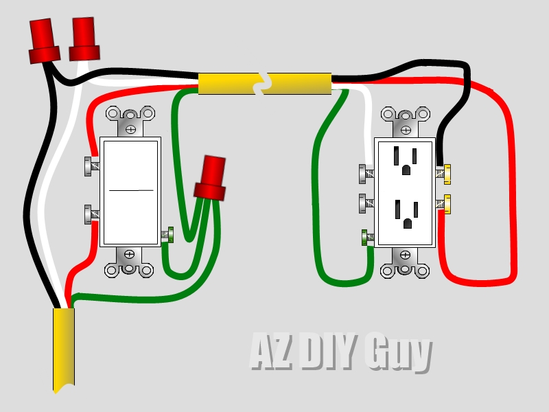
Switched Outlet Wiring Diagram is a useful tool for understanding how electrical outlets are wired in a building. It provides a visual representation of the connections between the various components involved in powering an outlet.
Why Switched Outlet Wiring Diagram are essential
- Helps electricians and DIY enthusiasts understand the layout of electrical outlets
- Ensures proper wiring and connections for safe operation
- Aids in troubleshooting electrical problems
- Complies with electrical codes and regulations
How to read and interpret Switched Outlet Wiring Diagram
Switched Outlet Wiring Diagrams typically include symbols and labels to represent different components such as switches, outlets, and wires. Here are some tips for effectively interpreting these diagrams:
- Understand the symbols used in the diagram
- Follow the flow of electricity from the power source to the outlet
- Identify the connections and wiring configurations
- Refer to the legend or key for clarification on symbols and labels
Using Switched Outlet Wiring Diagram for troubleshooting
Switched Outlet Wiring Diagrams can be invaluable when diagnosing and fixing electrical issues. By following the diagram, you can pinpoint the source of the problem and make the necessary repairs. Here’s how these diagrams can help with troubleshooting:
- Identify faulty connections or wiring issues
- Locate the switch or outlet causing the problem
- Compare the diagram to the actual setup to find discrepancies
- Test circuits and components based on the diagram’s guidance
Safety tips when working with Switched Outlet Wiring Diagram
When working with electrical systems and using wiring diagrams, safety should always be a top priority. Here are some important tips to ensure your safety:
- Turn off the power supply before working on any electrical components
- Use insulated tools to prevent electric shock
- Wear protective gear such as gloves and goggles
- Double-check all connections before restoring power
Switched Outlet Wiring Diagram
Wiring Diagram For Switched Outlet

An Electrician Explains How to Wire a Switched (Half-Hot) Outlet

How To Wire A Switched Outlet Power To Receptacle

wiring a switched outlet diagram Receptacle wiring diagram / electrical

3 Way Switched Outlet Wiring Diagram – 3 Way Switch Wiring Diagram

How To Wire Combination Switch Outlet – Switched Outlet Wiring Diagram

Wiring A Switched Outlet With 3 Wire

how to install electrical switch and outlet – Wiring Work
