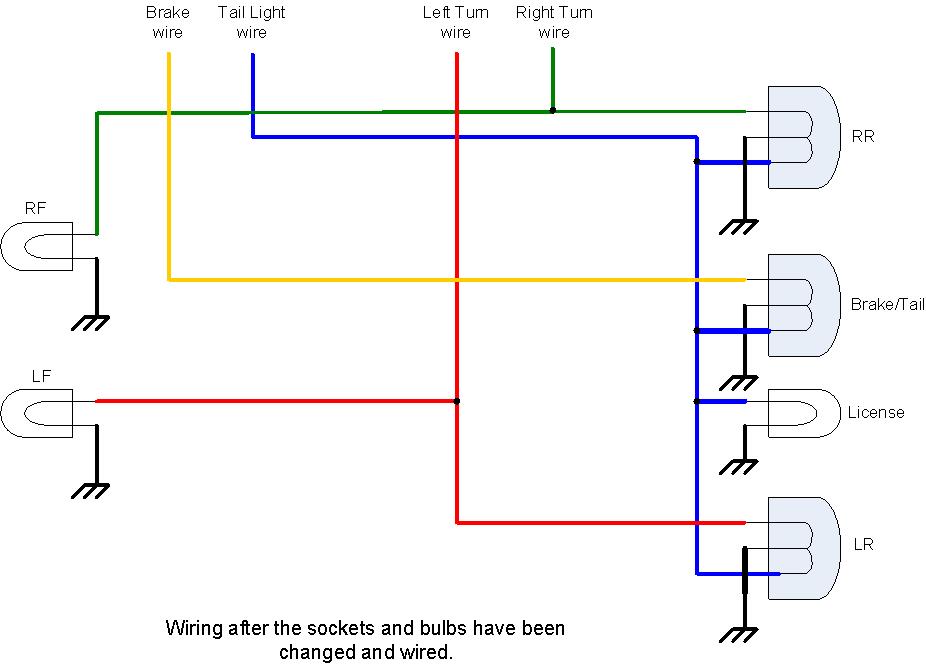
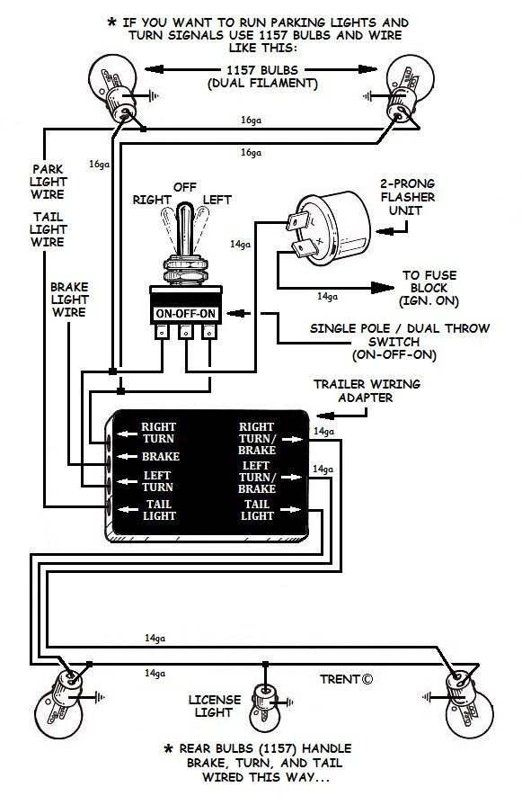
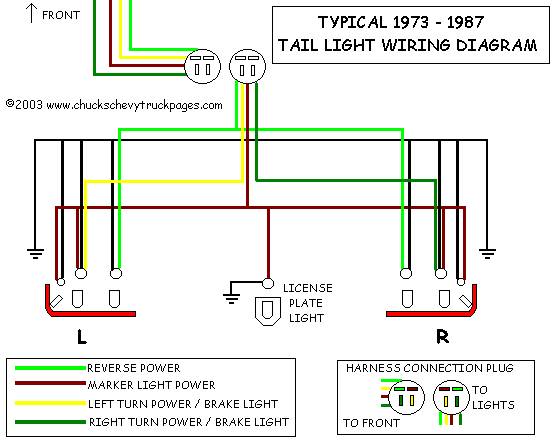
When it comes to understanding the electrical system of a vehicle, having a clear understanding of the Stop Turn Tail Light Wiring Diagram is essential. This diagram provides a detailed layout of how the stop, turn, and tail lights are connected to the vehicle’s electrical system, helping to ensure that these lights function properly.
Why Stop Turn Tail Light Wiring Diagrams are Essential
- Ensure proper functioning of stop, turn, and tail lights
- Help diagnose and troubleshoot electrical issues
- Provide a guide for installing or replacing lights
- Ensure compliance with safety regulations
Reading and Interpreting Stop Turn Tail Light Wiring Diagrams
Stop Turn Tail Light Wiring Diagrams may seem complex at first glance, but with a little guidance, they can be easily understood. Here are some key points to keep in mind:
- Identify the color codes for each wire
- Understand the symbols and abbreviations used in the diagram
- Follow the flow of electricity from the power source to the lights
- Pay attention to the connections and components involved
Using Stop Turn Tail Light Wiring Diagrams for Troubleshooting
When faced with electrical issues related to the stop, turn, or tail lights, the wiring diagram can be a valuable tool for troubleshooting. Here’s how you can use the diagram effectively:
- Identify any loose or damaged connections
- Check for continuity in the wiring using a multimeter
- Trace the flow of electricity to pinpoint the source of the problem
- Refer to the diagram to ensure proper reconnection of wires
Importance of Safety
Working with electrical systems can be dangerous if proper precautions are not taken. When using Stop Turn Tail Light Wiring Diagrams, it’s important to prioritize safety. Here are some safety tips to keep in mind:
- Always disconnect the battery before working on the electrical system
- Use insulated tools to prevent electric shock
- Avoid working on the wiring when the vehicle is running
- Double-check all connections before turning on the lights
Stop Turn Tail Light Wiring Diagram
Stop Tail Turn Wiring Diagram

Stop Turn Tail Light Wiring Diagram

Stop/Turn/Tail Light Wiring Diagram : 3 Wire Trailer Wiring Diagram

92 Chevy K1500 Tail Lights Wiring Diagram – ChevyWiringDiagram.com

Stock tail/stop lights for turn signals – Page 2

Tail Light Wiring Diagram – Cadician's Blog

Headlight And Tail Light Wiring Schematic / Diagram – Typical 1973

Truck Tail Light Wiring Diagram
