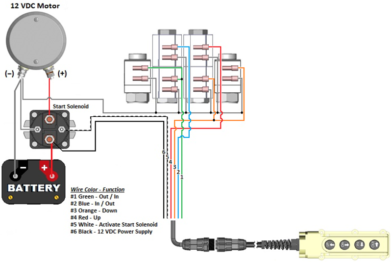
When it comes to understanding the inner workings of hydraulic systems, the Solenoid 12 Volt Hydraulic Pump Wiring Diagram is a crucial tool. This diagram provides a visual representation of how the electrical components of the hydraulic pump are connected and function together, helping mechanics troubleshoot and repair any issues that may arise.
Why Solenoid 12 Volt Hydraulic Pump Wiring Diagrams are Essential
Understanding the wiring diagram of a solenoid 12 volt hydraulic pump is essential for several reasons:
- Helps identify the various electrical components of the hydraulic system
- Guides in troubleshooting electrical issues efficiently
- Ensures proper installation and maintenance of the hydraulic pump
How to Read and Interpret Solenoid 12 Volt Hydraulic Pump Wiring Diagrams
Reading and interpreting a solenoid 12 volt hydraulic pump wiring diagram may seem daunting at first, but with some guidance, it becomes much easier:
- Identify the key components such as the solenoid, battery, pump motor, and ground connection
- Follow the wiring paths to understand how the components are connected
- Refer to the legend or key for any symbols or colors used in the diagram
Using Solenoid 12 Volt Hydraulic Pump Wiring Diagrams for Troubleshooting
When encountering electrical problems with a hydraulic pump, the wiring diagram can be a valuable tool for troubleshooting:
- Check for any loose or disconnected wires as per the diagram
- Test the continuity of wires to ensure proper connections
- Refer to the diagram to identify any faulty components that may need replacement
Safety Tips for Working with Solenoid 12 Volt Hydraulic Pump Wiring Diagrams
When working with electrical systems and using wiring diagrams, safety should always be a top priority:
- Ensure the power source is disconnected before working on the hydraulic pump
- Use insulated tools to prevent electrical shocks
- Follow proper safety precautions and guidelines for working with electrical systems
Solenoid 12 Volt Hydraulic Pump Wiring Diagram
️12v Hydraulic Pump Wiring Diagram Free Download| Gambr.co

Hydraulic Pump Solenoid Wiring Diagram

Solenoid 12 Volt Hydraulic Pump Wiring Diagram

[DIAGRAM] Diagrams For 12 Volt Solenoid Wiring Systems – MYDIAGRAM.ONLINE
How to Wire Hydraulic Power Pack,Power Unit Diagram Design

Installation Instructions: 12 VDC Dual Double-Acting | KTI Hydraulics, Inc.

12 Volt Hydraulic Pump Wiring Diagram – exatin.info
