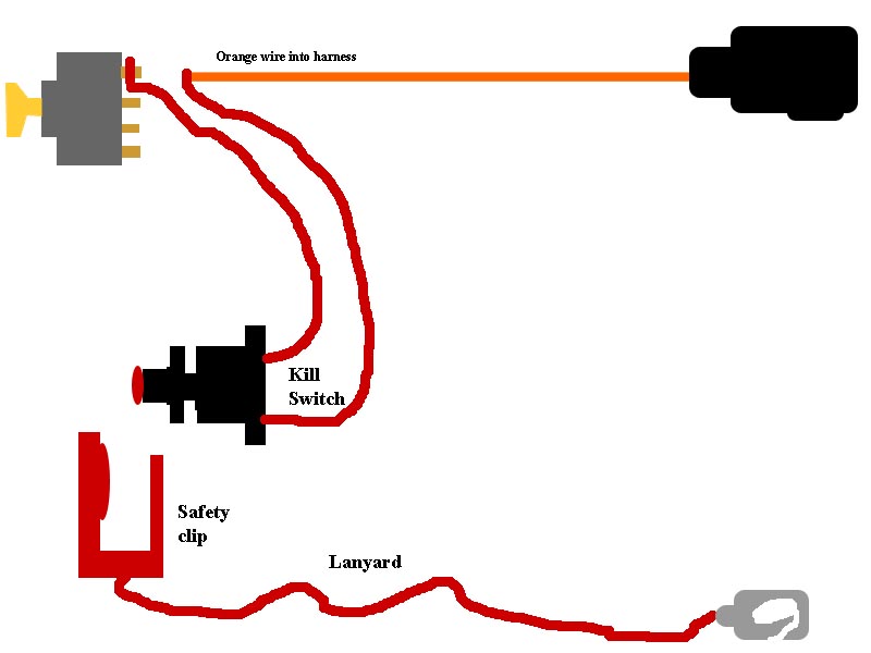
Small Engine Kill Switch Wiring Diagrams are essential tools for understanding the electrical systems of small engines. These diagrams provide a visual representation of how the kill switch is wired in the engine, making it easier to troubleshoot and repair any electrical issues that may arise.
Importance of Small Engine Kill Switch Wiring Diagrams
- Help identify the components of the kill switch system
- Show the connections between different parts of the electrical system
- Aid in diagnosing and fixing electrical problems
- Ensure proper installation and wiring of the kill switch
Reading and Interpreting Small Engine Kill Switch Wiring Diagrams
When looking at a Small Engine Kill Switch Wiring Diagram, it’s important to understand the symbols and color codes used. Here are some key points to keep in mind:
- Follow the lines to see how components are connected
- Refer to the legend for symbol meanings
- Pay attention to colors to identify different wires
- Use a multimeter to test for continuity and voltage
Using Small Engine Kill Switch Wiring Diagrams for Troubleshooting
Small Engine Kill Switch Wiring Diagrams can be invaluable when troubleshooting electrical problems. Here’s how you can use them effectively:
- Identify the kill switch and related components on the diagram
- Trace the wiring to check for loose connections or damaged wires
- Compare the diagram to the actual wiring in the engine
- Use the diagram to test for continuity and voltage at different points
Safety Tips for Working with Small Engine Kill Switch Wiring Diagrams
When working with small engine electrical systems and wiring diagrams, it’s important to prioritize safety. Here are some tips to keep in mind:
- Always disconnect the battery before working on the electrical system
- Wear insulated gloves and protective eyewear to prevent electrical shock
- Double-check all connections before powering up the engine
- Refer to the manufacturer’s guidelines for proper wiring and installation
Small Engine Kill Switch Wiring Diagram
Kill Switch Wiring Diagram

How To Fit A Kill-Switch | Boat Fittings

How To Quickly Install A Motorcycle Kill Switch In 1 Hour

Small Engine Key Switch Wiring

Small Engine Kill Switch Wiring Diagram

Kill Switch Wiring Diagram Car – Wiring Digital and Schematic
How To Fit A Kill-Switch | Boat Fittings

Starter Kill Switch Wiring Diagram
