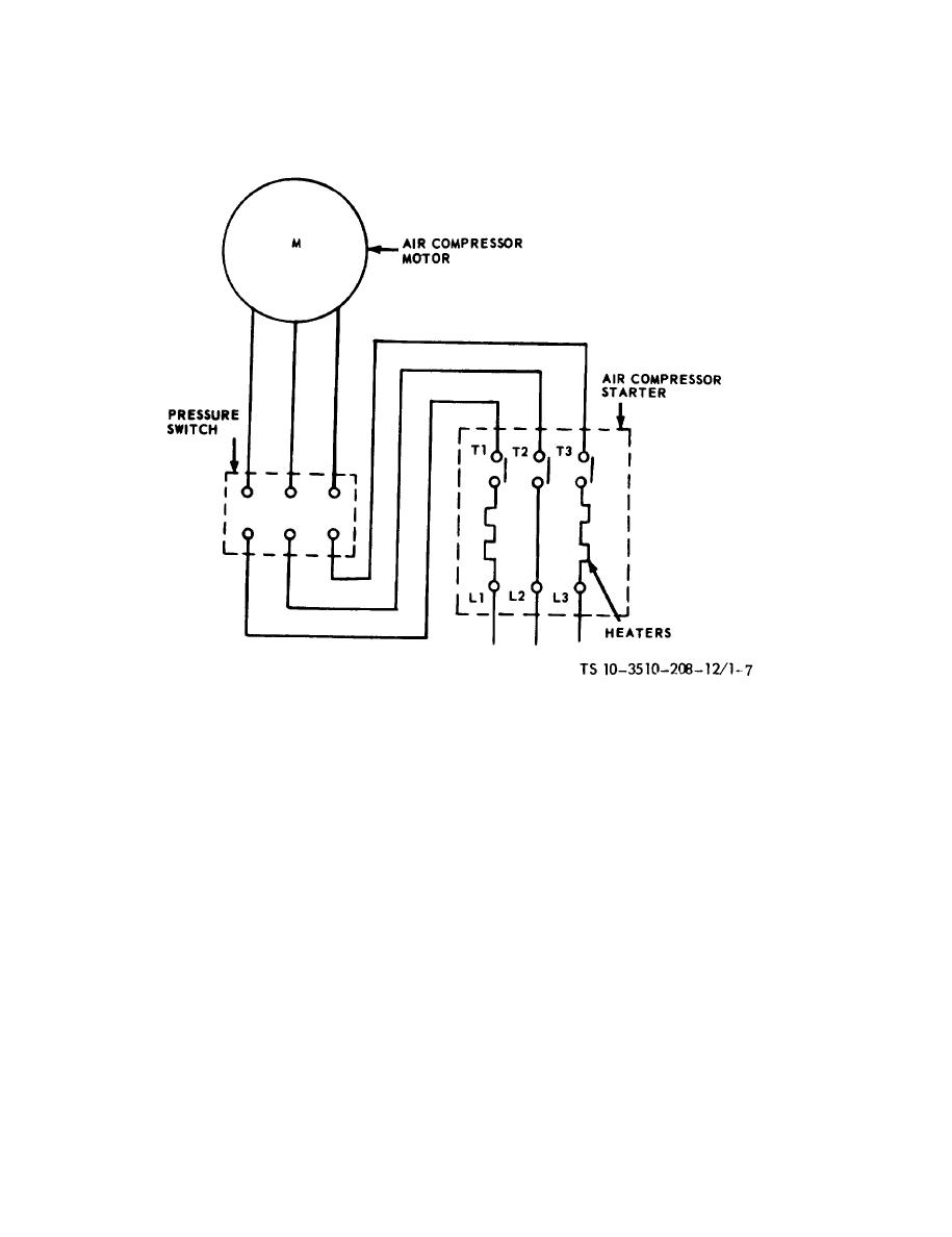
Single Phase Compressor Wiring Diagram is a crucial tool for anyone working with air compressors or other electrical systems. It provides a visual representation of the electrical connections and functions of the compressor, helping users understand how to properly wire and troubleshoot the system.
Why Single Phase Compressor Wiring Diagrams are essential
- Ensure proper wiring of the compressor motor
- Help prevent electrical malfunctions and damage
- Aid in troubleshooting electrical issues
Reading and interpreting Single Phase Compressor Wiring Diagram
When looking at a Single Phase Compressor Wiring Diagram, it’s important to pay attention to the symbols, colors, and connections. Here are some tips for reading and interpreting the diagram effectively:
- Identify the main components such as the compressor motor, start relay, capacitor, and power supply
- Follow the flow of the electrical connections from the power source to the motor
- Understand the function of each wire and connection point
Using Single Phase Compressor Wiring Diagram for troubleshooting
Single Phase Compressor Wiring Diagrams are invaluable when it comes to troubleshooting electrical problems. By following the diagram and checking the connections, users can quickly identify and fix issues such as faulty wiring, broken components, or incorrect connections.
Safety tips when working with Single Phase Compressor Wiring Diagram
When working with electrical systems and using wiring diagrams, safety should always be a top priority. Here are some safety tips and best practices to keep in mind:
- Always turn off the power supply before working on the compressor
- Use insulated tools to prevent electrical shocks
- Double-check all connections before turning the power back on
- If you are unsure or uncomfortable with electrical work, seek help from a professional
Single Phase Compressor Wiring Diagram
Single Phase Ac Compressor Wiring Diagram

Single Phase Compressor Wiring With Capacitor

Single Phase 220 Volt Air Compressor Wiring Diagram

Single Phase 220 Volt Air Compressor Wiring Diagram

Ac 110v Single Phasepressor Wiring Diagram

Single Phase Compressor Wiring Schematics

Single Phase Ac Compressor Wiring Diagram

How To Wire A Single Phase Compressor
