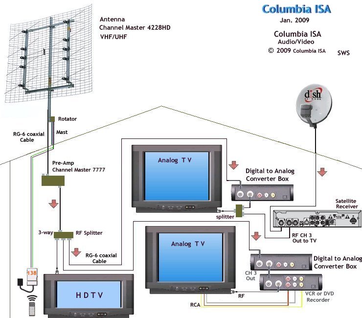
Rv Tv Antenna Booster Wiring Diagram
An Rv Tv Antenna Booster Wiring Diagram is a visual representation of the electrical connections and components in an RV’s TV antenna booster system. It is essential for understanding how the system is wired, troubleshooting electrical problems, and making modifications or repairs.
Why are Rv Tv Antenna Booster Wiring Diagrams essential?
- Provide a clear overview of the electrical connections in the system
- Help in identifying faulty components or wiring issues
- Assist in making modifications or upgrades to the system
- Ensure proper installation and operation of the TV antenna booster
How to read and interpret Rv Tv Antenna Booster Wiring Diagrams effectively
- Start by familiarizing yourself with the symbols and colors used in the diagram
- Follow the flow of the wiring from the power source to the components
- Pay attention to the labels and descriptions of each component or connection
- Refer to the legend or key for any abbreviations or special symbols used
Using Rv Tv Antenna Booster Wiring Diagrams for troubleshooting electrical problems
- Identify the specific area or component of the system where the issue may be occurring
- Trace the wiring to check for any loose connections, breaks, or short circuits
- Refer to the diagram to determine the proper voltage or signal levels at each point in the system
- Consult with a professional if the issue cannot be resolved by following the diagram
When working with Rv Tv Antenna Booster Wiring Diagrams, it is crucial to prioritize safety at all times. Here are some tips and best practices to ensure a safe working environment:
- Always disconnect the power source before working on any electrical connections
- Use insulated tools and equipment to prevent electric shock
- Avoid working in wet or damp conditions to reduce the risk of electrical hazards
- Double-check your work and connections before energizing the system
Rv Tv Antenna Booster Wiring Diagram
Rv Tv Antenna Booster Wiring Diagram – Wiring Diagram

Rv Tv Wiring Diagram

Antenna HDTV DTV analog hookup wiring TV

Rv Tv Antenna Booster Wiring Diagram – Easy Wiring

rv tv antenna booster wiring diagram Vcr rv ins dtv – Wiring Diagram

RV Cable TV Wiring Diagram: 5 Best Connection Options

How to Make RV TV Antenna Booster? – RVing Beginner

RV Cable TV Wiring Diagram: 5 Best Connection Options
