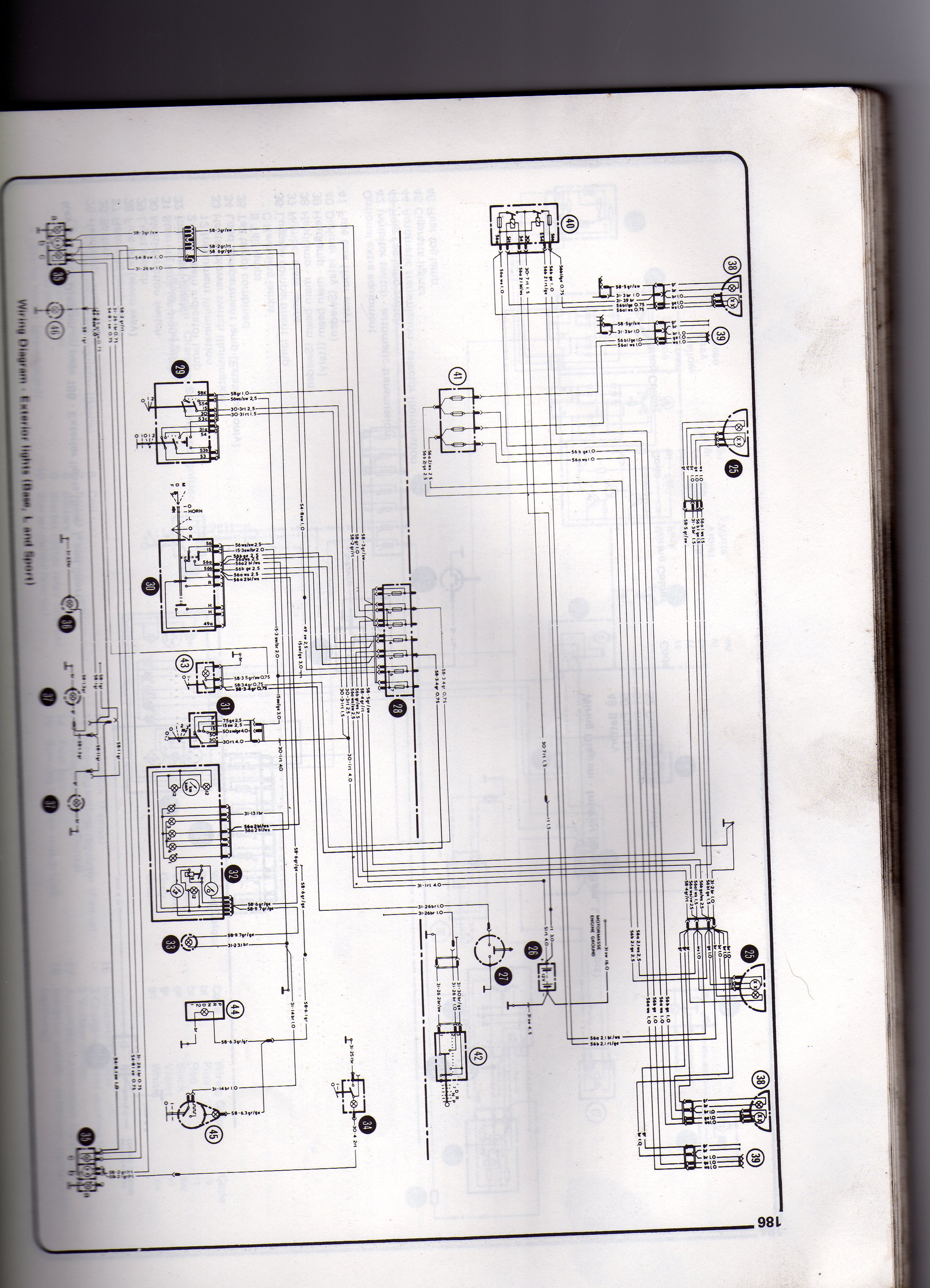
Rotork Wiring Diagrams are essential tools for anyone working with electrical systems, especially in the context of Rotork actuators. These diagrams provide a visual representation of the electrical connections within the device, making it easier to understand how the components are wired together.
Why Rotork Wiring Diagrams are essential
- Helps in understanding the electrical connections within the device
- Aids in troubleshooting electrical issues
- Ensures proper installation and maintenance of the device
Reading and interpreting Rotork Wiring Diagrams
When looking at a Rotork Wiring Diagram, it’s important to understand the symbols and codes used to represent different components. Typically, the diagram will include labels for each wire, connections between components, and any other relevant information. By familiarizing yourself with these elements, you can easily follow the electrical pathways and identify potential issues.
Using Rotork Wiring Diagrams for troubleshooting
Rotork Wiring Diagrams are invaluable when it comes to troubleshooting electrical problems. By tracing the connections outlined in the diagram, you can pinpoint the source of the issue and take appropriate action. Whether it’s a faulty wire, a disconnected component, or a damaged connection, the diagram provides a roadmap for solving the problem efficiently.
Importance of safety
Working with electrical systems can be dangerous, so it’s crucial to prioritize safety at all times. When using Rotork Wiring Diagrams, make sure to follow these safety tips:
- Always turn off the power before working on any electrical equipment
- Use insulated tools to prevent electrical shock
- Wear appropriate protective gear, such as gloves and goggles
- Double-check your work to ensure all connections are secure before turning the power back on
Rotork Wiring Diagram
Rotork Wiring Diagram Pdf Circuit Of Ceiling Fan

Rotork Iqt 2000 Wiring Diagram – Organicist

Rotork Mov Wiring Diagram – Wiring Diagram Pictures

Rotork Valve Wiring Diagram – Esquilo.io

rotork wiring diagrams

Rotork Motor Operated Valve Basic Configuration

Sony Xplod Cdx Ca650x Wiring Diagram – rotork wiring diagram

Rotork Actuator Wiring Diagram
