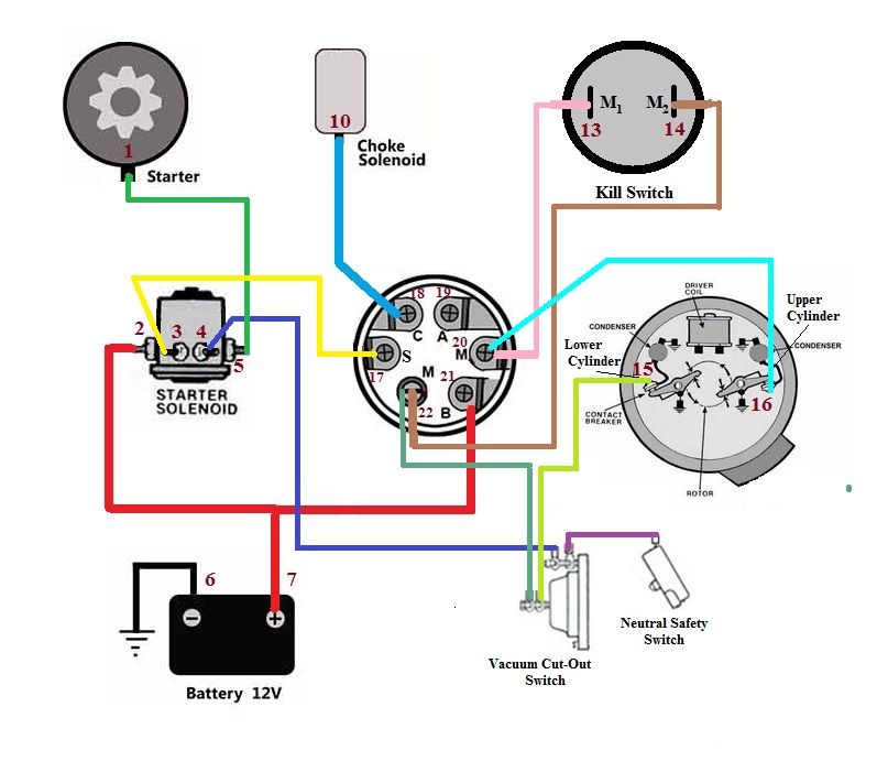
Welcome to this informative article about Riding Mower 7 Prong Ignition Switch Wiring Diagram. Riding mower ignition switch wiring diagrams are crucial for understanding the electrical system of your riding mower and ensuring proper functionality.
Why Riding Mower 7 Prong Ignition Switch Wiring Diagrams are Essential
Understanding the wiring diagram of your riding mower’s ignition switch is essential for several reasons:
- Helps in diagnosing electrical issues
- Guides in proper installation of new ignition switches
- Ensures correct connections for smooth operation
Reading and Interpreting Riding Mower 7 Prong Ignition Switch Wiring Diagram
Reading and interpreting a riding mower ignition switch wiring diagram may seem daunting at first, but with some guidance, it becomes easier:
- Identify the components and connections
- Understand the wiring color codes
- Follow the flow of the electrical current
Using Riding Mower 7 Prong Ignition Switch Wiring Diagram for Troubleshooting
Riding mower ignition switch wiring diagrams are invaluable when troubleshooting electrical problems:
- Locate faulty connections or components
- Check for continuity and proper voltage levels
- Trace the path of the electrical circuit to pinpoint the issue
Importance of Safety
When working with electrical systems and using wiring diagrams, safety should always be a top priority:
- Turn off the power source before working on any electrical components
- Use insulated tools to prevent electrical shocks
- Avoid working in wet or damp conditions
- Double-check all connections before restoring power
Riding Mower 7 Prong Ignition Switch Wiring Diagram
7 Prong Lawn Mower Ignition Switch Wiring Diagram

Lawn Mower 7 Terminal Ignition Switch Wiring Diagram

Lawn Mower 7 Terminal Key Switch Diagram – IGNITION KEY SWITCH fits

7 Prong Ignition Switch Wiring Diagram

craftsman 7 terminal ignition switch wiring diagram

How do I test the 7 prong ignition switch, 1 day, yes, no

ignition switch wiring diagram for lawn mower Ignition switch wiring

Lawn Tractor Ignition Systems And How They Work. – TodaysMower.com
