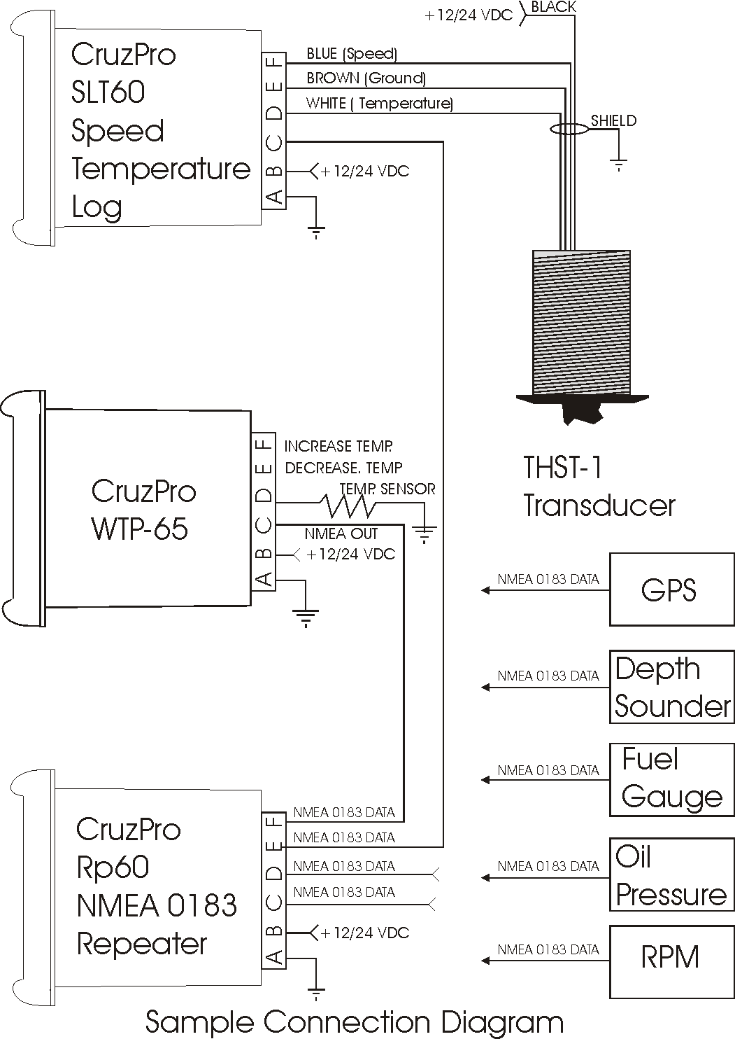
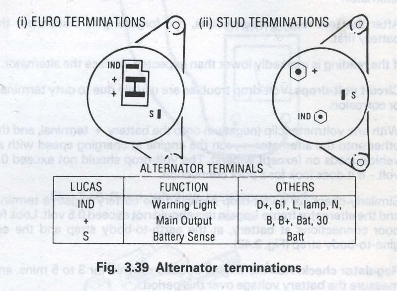
When working on a vehicle’s electrical system, understanding the Rev Counter Wiring Diagram is crucial for identifying and resolving issues. The Rev Counter Wiring Diagram provides a visual representation of the connections and components involved in the rev counter circuit, helping mechanics diagnose and troubleshoot problems effectively.
Why Rev Counter Wiring Diagrams are Essential
Rev Counter Wiring Diagrams are essential for several reasons:
- Help identify the wiring connections of the rev counter
- Aid in diagnosing electrical issues related to the rev counter
- Provide guidance for installing or replacing rev counter components
- Ensure proper wiring connections for optimal performance
Reading and Interpreting Rev Counter Wiring Diagrams
Reading and interpreting Rev Counter Wiring Diagrams may seem daunting at first, but with some guidance, it becomes easier:
- Understand the symbols and abbreviations used in the diagram
- Follow the flow of the wiring from the power source to the rev counter
- Identify the components and their connections within the circuit
- Pay attention to the color-coding of wires for accurate interpretation
Using Rev Counter Wiring Diagrams for Troubleshooting
Rev Counter Wiring Diagrams are invaluable tools for troubleshooting electrical problems:
- Pinpoint the location of faulty connections or components
- Verify the continuity of wires and connections within the circuit
- Check for voltage drops or irregularities that may affect the rev counter’s operation
- Aid in isolating the source of the problem for efficient repairs
- Disconnect the vehicle’s battery before starting any electrical work
- Use insulated tools to prevent electric shock
- Avoid working on wet or damp surfaces to prevent electrocution
- Double-check all connections before reapplying power to the system
Safety Tips and Best Practices
When working with electrical systems and using wiring diagrams, safety should always be a top priority:
Rev Counter Wiring Diagram
Racetech Rev Counter Wiring Diagram – Wiring Diagram

Auto Gauge Rev Counter Wiring Diagram

A Visual Guide to the Wiring Diagram of Smiths Rev Counter

[DIAGRAM] Auto Gauge Rev Counter Wiring Diagram – MYDIAGRAM.ONLINE
![Rev Counter Wiring Diagram [DIAGRAM] Auto Gauge Rev Counter Wiring Diagram - MYDIAGRAM.ONLINE](https://i1.wp.com/wiringall.com/image/vdo-rev-counter-wiring-diagram-6.png)
Vdo Rev Counter Wiring Diagram

Auto Gauge Rev Counter Wiring Diagram

Nissan 1400 Rev Counter Wiring Diagram
rev counter wiring?
