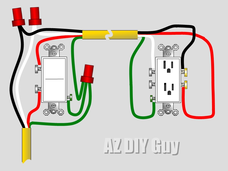
Receptacle Wiring Diagrams are essential tools for understanding the electrical connections of outlets in a building. By providing a visual representation of the wiring configuration, these diagrams help electricians and DIY enthusiasts properly install, troubleshoot, and repair electrical outlets.
Why Receptacle Wiring Diagrams are Essential
Receptacle Wiring Diagrams are crucial for several reasons:
- Ensure proper installation of outlets
- Identify wiring errors or faults
- Aid in troubleshooting electrical issues
- Comply with building codes and safety standards
How to Read and Interpret Receptacle Wiring Diagrams
Reading and interpreting receptacle wiring diagrams can be daunting for beginners, but with the following tips, it becomes easier:
- Understand the symbols and abbreviations used in the diagram
- Follow the flow of electricity from the power source to the outlet
- Identify the hot, neutral, and ground wires
- Pay attention to the color-coding of wires
Using Receptacle Wiring Diagrams for Troubleshooting
When faced with electrical problems, receptacle wiring diagrams can be a lifesaver. Here’s how you can use them for troubleshooting:
- Trace the wiring to identify any loose connections or damaged wires
- Check for continuity using a multimeter
- Compare the actual wiring with the diagram to pinpoint the issue
- Follow the wiring sequence to ensure proper connections
Safety Tips for Working with Receptacle Wiring Diagrams
Working with electrical systems can be dangerous, so it’s crucial to prioritize safety at all times. Here are some safety tips when using receptacle wiring diagrams:
- Always turn off the power before working on electrical outlets
- Wear appropriate personal protective equipment, such as gloves and goggles
- Double-check your work before turning the power back on
- Consult a professional if you’re unsure about any aspect of the wiring diagram
Receptacle Wiring Diagram
How To Wire An Electrical Outlet Wiring Diagram | House Electrical

An Electrician Explains How to Wire a Switched (Half-Hot) Outlet

Residential Receptacle Wiring Diagram

Basic Ac Wiring Receptacle

Electrical – How to wire several receptacles between three-way switches

Receptacle Wiring Diagrams Made Simple

Nema 6 20p Wiring Diagram – Wiring Diagram

240v Receptacle Wiring Diagram
