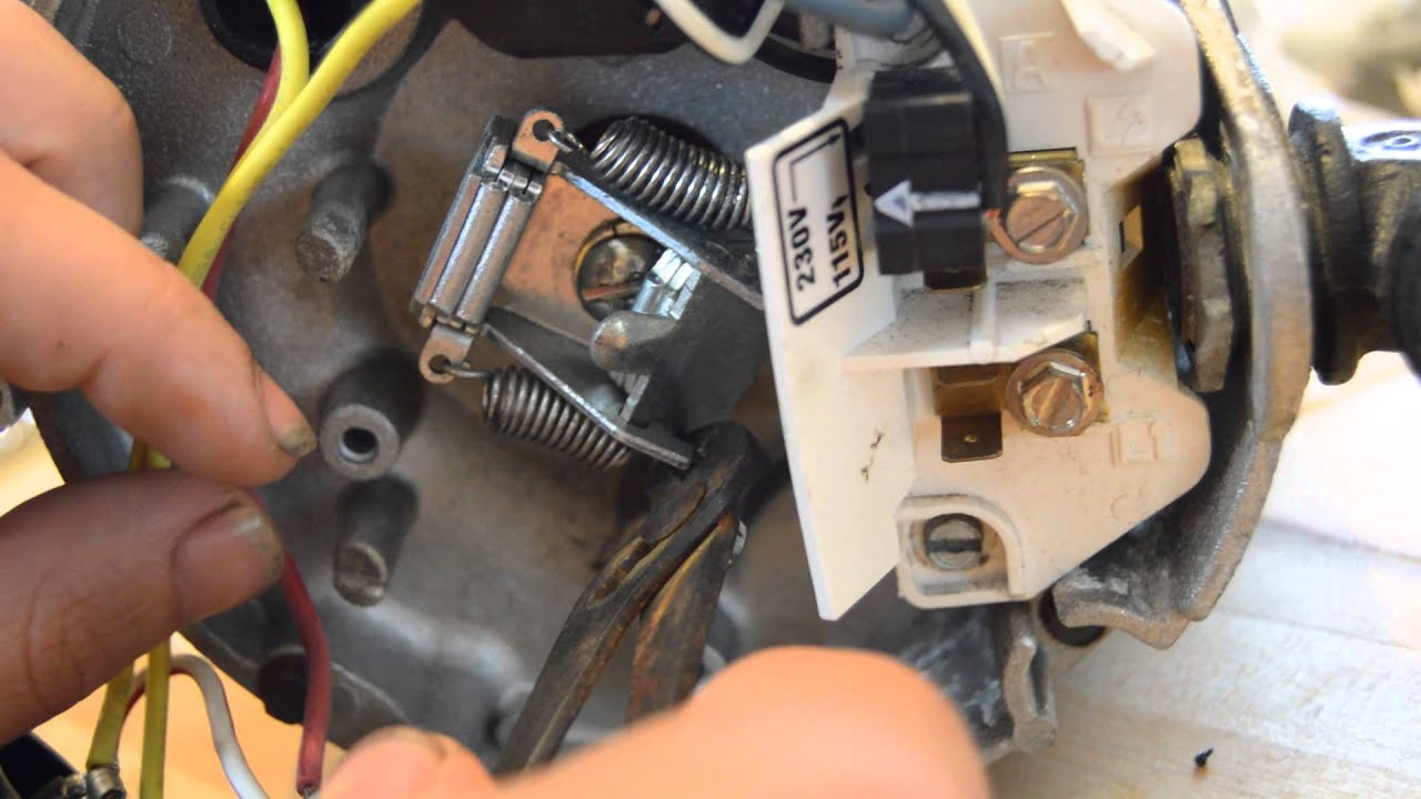
Pool Pump Timer Wiring Diagram is a crucial tool for anyone looking to install, repair, or troubleshoot their pool pump timer. It provides a visual representation of the electrical connections and components involved in the operation of the timer, helping users understand how everything is connected and functioning.
Importance of Pool Pump Timer Wiring Diagram
Understanding the Pool Pump Timer Wiring Diagram is essential for several reasons:
- Ensures proper installation of the pool pump timer
- Aids in troubleshooting electrical issues
- Helps in identifying faulty components
- Ensures safety during maintenance and repairs
Reading and Interpreting Pool Pump Timer Wiring Diagram
When looking at a Pool Pump Timer Wiring Diagram, it’s important to pay attention to the following:
- Color coding of wires
- Connection points for various components
- Switches, relays, and other control devices
- Power supply and ground connections
Using Pool Pump Timer Wiring Diagram for Troubleshooting
Pool Pump Timer Wiring Diagrams are invaluable when troubleshooting electrical problems. By following the diagram, you can:
- Identify loose or disconnected wires
- Locate faulty components such as switches or relays
- Check for continuity and proper voltage levels
- Verify correct wiring connections
Safety Tips for Working with Pool Pump Timer Wiring Diagram
When working with electrical systems and using wiring diagrams, it’s crucial to prioritize safety. Here are some safety tips and best practices to keep in mind:
- Always turn off the power supply before working on any electrical components
- Use insulated tools to prevent electric shock
- Avoid working in wet or damp conditions
- Double-check all connections before turning the power back on
- If you’re unsure about any step, consult a professional electrician
Pool Pump Timer Wiring Diagram
Grasslin Pool Timer Wiring Diagram – Wiring Diagram
Intermatic Pool Timer Wiring Diagram Load Management

Understanding 120V Intermatic Timer Wiring Diagrams – Wiring Diagram

33 Pool Pump Wiring Diagram – Wiring Diagram Info

How To Wire A Pool Pump Switch

Grasslin Timer Wiring Diagram Free Download | Manual E-Books

115v Pool Pump Timer Wiring Diagram – inspireque

How to install a pool pump timer? – 6 Steps – SwimPoolHub
