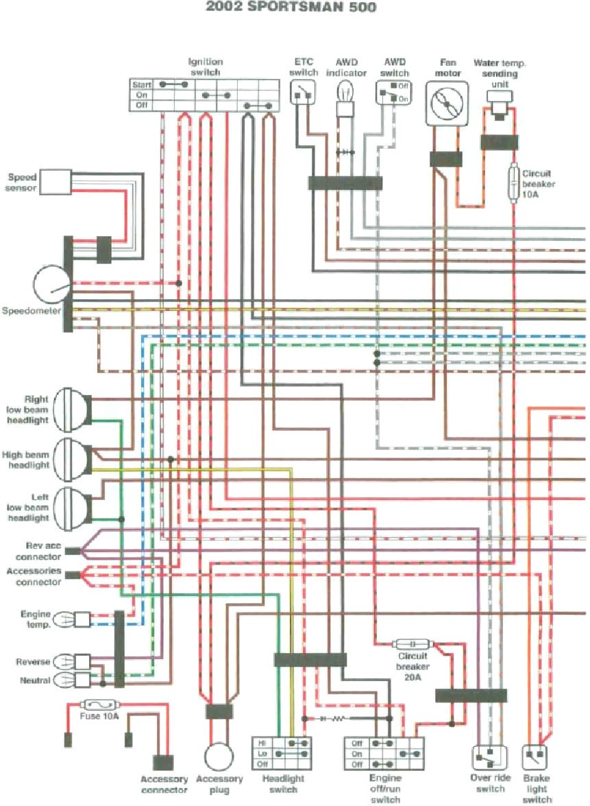
Are you looking to understand the intricacies of Polaris Cdi Wiring Diagram? These diagrams are crucial for anyone working on Polaris vehicles as they provide a detailed map of the electrical system. By studying these diagrams, you can gain insight into how different components are connected and how signals flow throughout the system.
Why Polaris Cdi Wiring Diagram are essential
- Helps in understanding the electrical system of the vehicle
- Aids in diagnosing and troubleshooting electrical issues
- Provides a roadmap for installing new components
How to read and interpret Polaris Cdi Wiring Diagram effectively
When looking at a Polaris Cdi Wiring Diagram, it’s important to familiarize yourself with the symbols and colors used. Each symbol represents a specific component, while colors indicate different wires or connections. By understanding these basics, you can easily follow the flow of electricity through the system and identify any potential issues.
Using Polaris Cdi Wiring Diagram for troubleshooting electrical problems
- Locate the component causing the issue on the diagram
- Follow the wiring path to identify any potential faults or breaks
- Use a multimeter to test for continuity and voltage at various points
- Compare your findings with the diagram to pinpoint the problem
Importance of safety when working with electrical systems
When dealing with electrical systems, it’s crucial to prioritize safety at all times. Here are some tips to keep in mind:
- Always disconnect the battery before working on the electrical system
- Wear insulated gloves and safety goggles to protect yourself from electrical shocks
- Double-check your connections before turning on the power
- Seek professional help if you’re unsure about any aspect of the wiring diagram
Polaris Cdi Wiring Diagram
Polaris Predator 90 Cdi Wiring Diagram – Wiring Diagram and Schematic Role

Polaris SLH 700: Q&A on CDI Wiring Diagram & Wire Color Code

Polaris CDI Wiring Diagram (Pictured & Explained) – Off-Road Official

Polaris CDI Wiring Diagram (Read And Understand)

Polaris Sportsman 500 Cdi Wiring Diagram – Wiring Diagram and Schematic

1999 Polaris Sportsman 500 Wiring Schematics – IOT Wiring Diagram

Polaris Predator 90 Cdi Wiring Diagram – Wiring Diagram and Schematic Role

8 Wire Cdi Wiring Diagram
