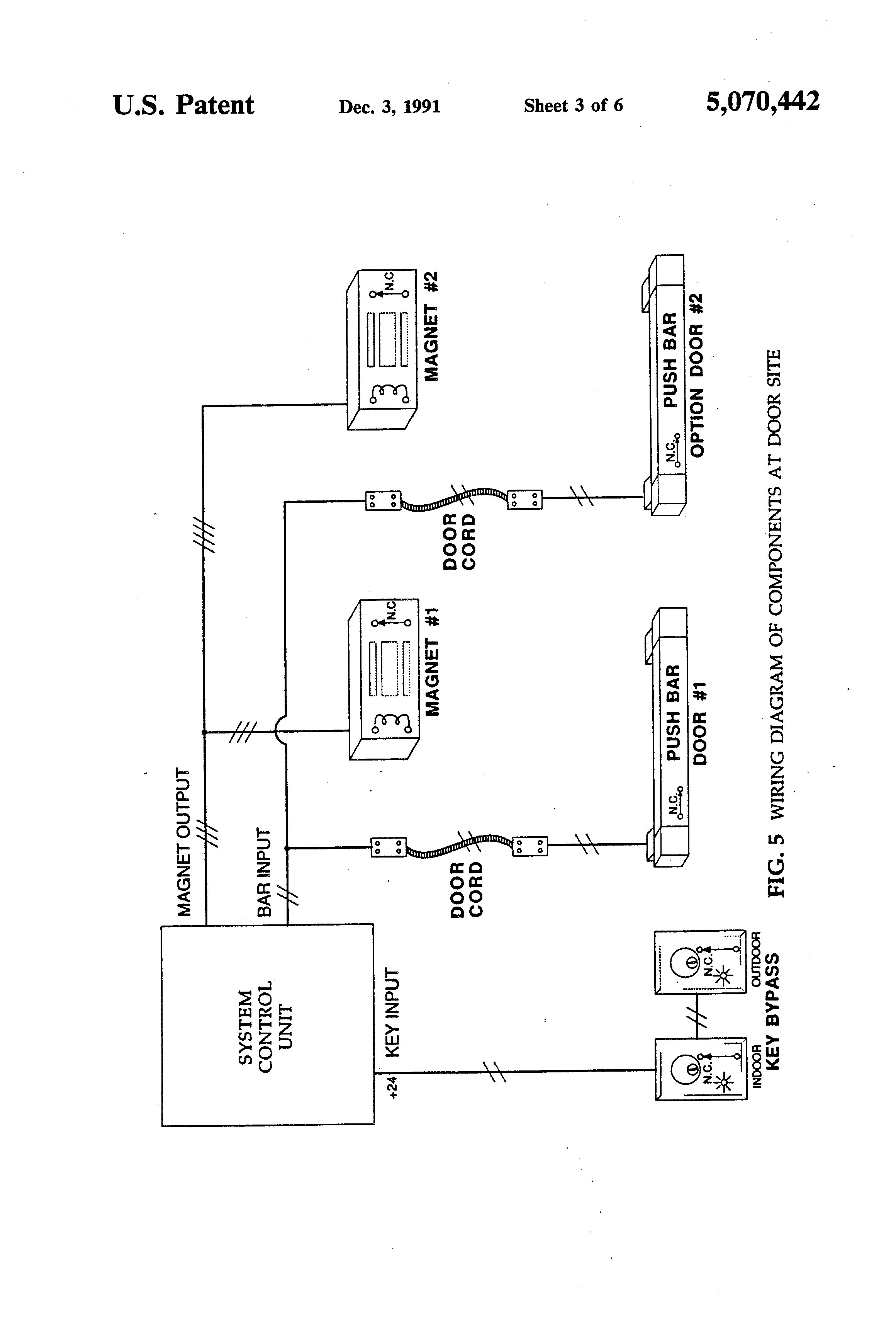
Parking Brake Bypass Wiring Diagram
A Parking Brake Bypass Wiring Diagram is a crucial tool for anyone working on electrical systems in a vehicle. It provides a visual representation of the wiring connections and circuits involved in bypassing the parking brake mechanism. This diagram is essential for understanding how the system works and how to safely make modifications.
Why Parking Brake Bypass Wiring Diagrams are Essential
- Helps to bypass safety features for aftermarket installations
- Allows for modifications to the parking brake system for specific needs
- Enables troubleshooting of electrical issues related to the parking brake mechanism
Reading and Interpreting Parking Brake Bypass Wiring Diagrams
When looking at a Parking Brake Bypass Wiring Diagram, it is important to understand the symbols and color-coding used. Each wire and connection has a specific purpose, and knowing how to interpret the diagram will help in making the necessary modifications accurately and safely.
Using Parking Brake Bypass Wiring Diagrams for Troubleshooting
- Identify the components involved in the parking brake system
- Trace the wiring connections to locate any faults or issues
- Refer to the diagram to understand how the system should function properly
Importance of Safety
Working with electrical systems can be dangerous, so it is essential to prioritize safety when using Parking Brake Bypass Wiring Diagrams. Here are some safety tips to keep in mind:
- Always disconnect the vehicle’s battery before working on any electrical components
- Use insulated tools to prevent electrical shocks
- Double-check all connections before reassembling the system
- Consult a professional if you are unsure about any modifications
Parking Brake Bypass Wiring Diagram
Alpine Parking Brake Bypass Wiring Diagram

Pioneer Parking Brake Bypass Wiring Diagram – Wiring Diagram

Understanding Pioneer Parking Brake Bypass Wiring Diagrams – Wiring Diagram

Parking Brake Wire Bypass(Pioneer Parking Brake Bypass DIY) – AutoVfix.com

Pioneer Parking Brake Bypass Wiring Diagram

Parking brake by pass?? – Ranger-Forums – The Ultimate Ford Ranger Resource

Understanding Pioneer Parking Brake Bypass Wiring Diagrams – Wiring Diagram

Pioneer Parking Brake Bypass Wiring Diagram Easywiring | My XXX Hot Girl
