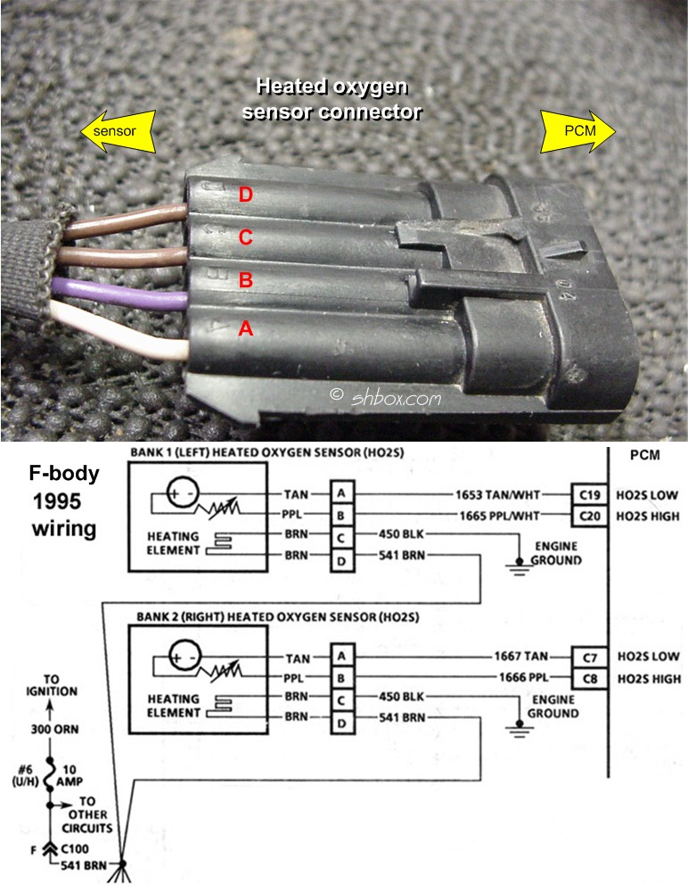
An Oxygen Sensor Wiring Diagram is a crucial tool for anyone working on automotive electrical systems. It provides a visual representation of the connections between the oxygen sensor and the vehicle’s electrical system, helping mechanics troubleshoot issues and make necessary repairs.
Why Oxygen Sensor Wiring Diagrams are Essential
Oxygen Sensor Wiring Diagrams are essential for several reasons:
- They help identify the correct wires and connectors for the oxygen sensor.
- They ensure proper installation and connection of the sensor to the vehicle’s electrical system.
- They assist in diagnosing and resolving issues related to the oxygen sensor, such as faulty connections or wiring problems.
How to Read and Interpret Oxygen Sensor Wiring Diagrams
Reading and interpreting Oxygen Sensor Wiring Diagrams requires some basic knowledge of electrical systems. Here are some tips to help you understand these diagrams:
- Identify the oxygen sensor and its corresponding connectors on the diagram.
- Follow the lines to trace the connections between the sensor and the vehicle’s electrical system.
- Pay attention to the color-coding of the wires, as different colors represent different functions.
Using Oxygen Sensor Wiring Diagrams for Troubleshooting
Oxygen Sensor Wiring Diagrams are invaluable for troubleshooting electrical problems related to the sensor. Here’s how you can use them effectively:
- Check for continuity between the sensor and the electrical system to ensure proper connection.
- Look for any signs of damage or wear on the wires that may be causing issues.
- Use a multimeter to test the voltage and resistance of the sensor to diagnose any malfunctions.
Importance of Safety
When working with electrical systems and using wiring diagrams, safety is paramount. Follow these safety tips and best practices to protect yourself and prevent accidents:
- Always disconnect the battery before working on any electrical components.
- Wear insulated gloves and eye protection to prevent electric shock.
- Avoid working on electrical systems in wet or damp conditions.
- Double-check all connections and wiring before reassembling components.
Oxygen Sensor Wiring Diagram
Bosch Oxygen Sensor Wiring Diagram

Oxygen Sensor: 1, 2, 3, 4 Wire O2 Sensor Wiring Diagram

Bosch 5 Wire Wideband O2 Sensor Wiring Diagram – Wiring Diagram

[8+] Oxygen Sensor Wiring Diagram, Oxygen Sensor Wiring
![Oxygen Sensor Wiring Diagram [8+] Oxygen Sensor Wiring Diagram, Oxygen Sensor Wiring](https://i1.wp.com/www.chanish.org/wp-content/uploads/2019/04/wiring_diagram_oxygen_sensor_0.jpg)
4 Wire Oxygen Sensor Wiring Diagram – Knittystash.com

Gm Oxygen Sensor Wiring Diagram

2003 Toyota Camry Oxygen Sensor Wiring Diagram – Wiring Diagram and
