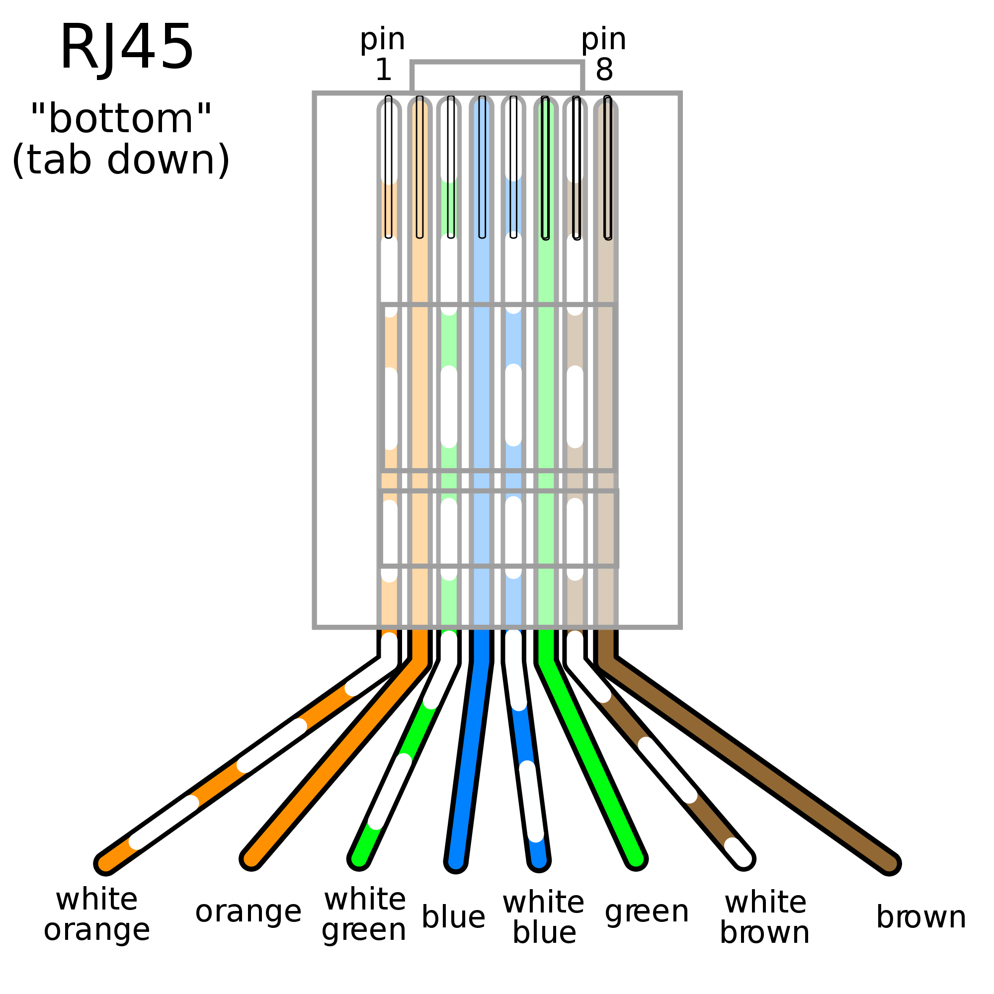
Network Wiring Diagrams are essential tools used in the field of networking to visually represent the layout of a network. These diagrams provide a detailed overview of how devices are connected and communicate with each other within a network. Understanding how to read and interpret these diagrams is crucial for technicians and engineers to effectively troubleshoot, maintain, and expand network systems.
Why Network Wiring Diagrams are essential:
- Helps in planning and designing network infrastructure
- Aids in troubleshooting connectivity issues
- Provides documentation for future reference and upgrades
- Ensures proper organization and labeling of network components
How to read and interpret Network Wiring Diagrams effectively:
When looking at a Network Wiring Diagram, it is important to understand the following key components:
- Network devices (routers, switches, servers, etc.)
- Connections between devices (Ethernet cables, fiber optic cables, wireless connections)
- IP addresses and subnets
- Network protocols and communication paths
Using Network Wiring Diagrams for troubleshooting electrical problems:
Network Wiring Diagrams can be invaluable when troubleshooting connectivity issues or electrical problems within a network. By following the paths of connections and identifying potential points of failure, technicians can quickly pinpoint and resolve issues. Some common troubleshooting steps include:
- Checking for loose connections or damaged cables
- Verifying correct IP configurations and subnet masks
- Testing network devices for functionality
- Utilizing network diagnostic tools for further analysis
Safety tips and best practices:
- Always turn off power before working on any electrical systems
- Use proper tools and equipment for handling wiring and connections
- Avoid working alone when dealing with electrical components
- Follow manufacturer’s guidelines and safety precautions
- Regularly inspect and maintain network wiring to prevent potential hazards
Network Wiring Diagram
Rj45 Wiring Diagram Cat5 | Ethernet wiring, Networking basics, Computer

Tia 568B Wiring Schema – Wiring Diagram Data – 568 B Wiring Diagram

Cat5e Network Cable Wiring Diagram – Unity Wiring

Network Cable in Colorado Springs – What Home & Business Owners Should

Network Diagram Software | Quickly Create High-quality Network Diagram

Logical And Physical Network Diagram

Ethernet Lan Wiring Diagram – Wiring Digital and Schematic

Network Cable Wiring Diagram 568A | Wiring Library – Ethernet Wiring
