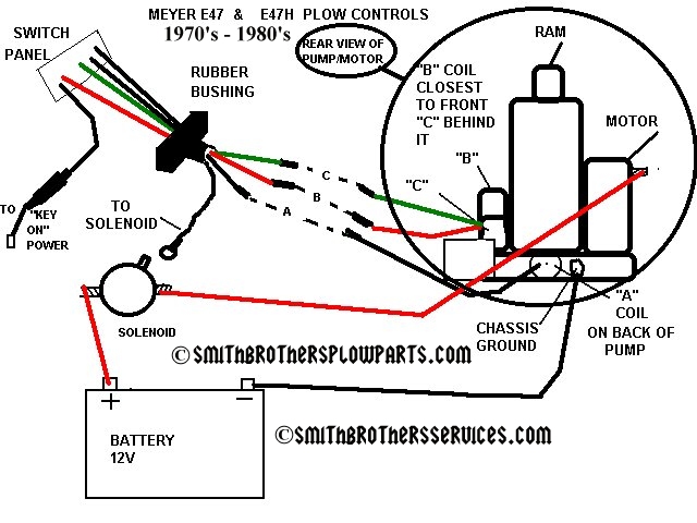
Are you looking for a comprehensive guide on Meyer Plow Wiring Diagram? Look no further! Meyer Plow Wiring Diagrams are essential tools for anyone working with Meyer plows to ensure proper installation, troubleshooting, and maintenance of the plow’s electrical system.
Why Meyer Plow Wiring Diagrams are Essential
Meyer Plow Wiring Diagrams are essential for the following reasons:
- They provide a visual representation of the electrical connections in the plow system.
- They help ensure proper installation of the plow components.
- They assist in troubleshooting electrical issues quickly and effectively.
Reading and Interpreting Meyer Plow Wiring Diagrams
When reading Meyer Plow Wiring Diagrams, it’s important to:
- Identify the components and their corresponding symbols in the diagram.
- Follow the wiring lines to understand the connections between the components.
- Refer to the key or legend to understand the color codes and labels used in the diagram.
Using Meyer Plow Wiring Diagrams for Troubleshooting
Meyer Plow Wiring Diagrams can be used for troubleshooting electrical problems by:
- Identifying the specific components or connections that may be causing the issue.
- Checking for continuity or voltage at different points in the system as indicated in the diagram.
- Following the wiring lines to trace the source of the problem and make necessary repairs.
Importance of Safety
When working with electrical systems and using wiring diagrams, safety should always be a top priority. Follow these safety tips and best practices:
- Always disconnect the power source before working on any electrical components.
- Use insulated tools to avoid electrical shocks.
- Avoid working in wet or damp conditions to prevent electrical hazards.
- Double-check your work and ensure all connections are secure before testing the system.
Meyer Plow Wiring Diagram
Meyer E-47.com – Meyer E-47 Snow Plow Pump Information, Parts Diagrams

Meyer snow plow wiring diagram e47

Meyer Snow Plow Wiring Diagram E47

Meyers Snow Plow Controller Wiring Diagram Pdf – Wiring Diagram and

42 meyers snow plows wiring diagram – Wiring Diagrams Manual
MeyerPlows.info – Meyer Plow Wiring Identification Information.

Meyer Plow Wiring Diagrams

Meyers Snow Plow Wiring Diagram E47 – General Wiring Diagram
