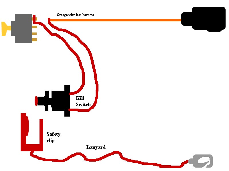
Mercury Kill Switch Wiring Diagrams are crucial tools for understanding the electrical systems in Mercury outboard motors. These diagrams provide a visual representation of how the kill switch is wired into the engine’s electrical system, helping mechanics and boat owners troubleshoot and repair any issues that may arise.
Why Mercury Kill Switch Wiring Diagrams are Essential
- Helps in understanding the electrical connections of the kill switch
- Aids in troubleshooting electrical problems
- Ensures proper installation and maintenance of the kill switch
- Provides a reference point for future repairs or modifications
Reading and Interpreting Mercury Kill Switch Wiring Diagrams
To effectively read and interpret Mercury Kill Switch Wiring Diagrams, it is important to understand the symbols and conventions used in the diagram. Pay attention to the color-coding, wire labels, and connection points to accurately follow the electrical paths and connections.
Using Mercury Kill Switch Wiring Diagrams for Troubleshooting
- Identify the kill switch wiring and connection points
- Check for continuity and proper voltage levels at each connection
- Compare the actual wiring with the diagram to pinpoint any discrepancies
- Use a multimeter to test the kill switch and related components for functionality
Importance of Safety
When working with electrical systems and using wiring diagrams, it is crucial to prioritize safety. Follow these safety tips and best practices to prevent accidents and ensure a successful repair process:
- Always disconnect the battery before working on electrical systems
- Use insulated tools to avoid electrical shock
- Wear appropriate safety gear, such as gloves and goggles
- Avoid working in wet or damp conditions to prevent electric shock
- Refer to the manufacturer’s guidelines and warnings for specific safety precautions
Mercury Kill Switch Wiring Diagram
Mercury Kill Switch Wiring Diagram
Mercury Kill Switch Wiring Diagram

Mercury Outboard Kill Switch Wiring Diagram Wiring Diagram Schemas | My

FiberGlassics® – How to hook a kill switch to an old Merc

How To Fit A Kill-Switch | Boat Fittings

[DIAGRAM] Mercury Outboard Wiring Diagram Kill Switch – MYDIAGRAM.ONLINE
![Mercury Kill Switch Wiring Diagram [DIAGRAM] Mercury Outboard Wiring Diagram Kill Switch - MYDIAGRAM.ONLINE](http://img404.imageshack.us/img404/8255/35electricstart.jpg)
Mercury kill switch wiring question – The Hull Truth – Boating and

Mercury Marine Kill Switch Wiring Diagram – Wiring Scan
