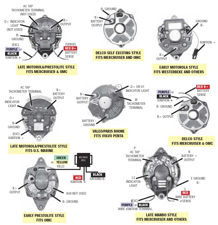
Marine Alternator Wiring Diagrams are crucial tools for understanding the electrical systems of marine vessels. These diagrams provide a visual representation of the wiring connections and components involved in the alternator system, helping mechanics and boat owners troubleshoot electrical issues and make necessary repairs.
Importance of Marine Alternator Wiring Diagrams
- Ensure proper installation of alternator and related components
- Identify correct wiring connections for optimal performance
- Troubleshoot electrical issues efficiently
- Prevent damage to electrical components due to incorrect wiring
Reading and Interpreting Marine Alternator Wiring Diagrams
Marine alternator wiring diagrams can seem complex at first glance, but with some guidance, they can be easily understood and utilized effectively. Here are some tips for reading and interpreting these diagrams:
- Pay attention to the symbols and color codes used in the diagram
- Follow the wiring paths to understand the connections between components
- Refer to the legend or key provided to identify different components
Using Marine Alternator Wiring Diagrams for Troubleshooting
When faced with electrical problems on a marine vessel, having access to the wiring diagram can be a lifesaver. Here’s how you can use the diagram for troubleshooting:
- Locate the specific circuit or component causing the issue on the diagram
- Trace the wiring to identify any damaged or loose connections
- Check for continuity and voltage at various points in the circuit
Safety Tips for Working with Marine Alternator Wiring Diagrams
Working with electrical systems on a marine vessel can be dangerous if proper safety precautions are not taken. Here are some safety tips to keep in mind:
- Ensure the power source is disconnected before working on the electrical system
- Use insulated tools to prevent shock hazards
- Avoid working in wet or damp conditions to prevent electrical shorts
- Double-check all connections before restoring power to the system
Marine Alternator Wiring Diagram
How to properly wire your Marine Alternator

Marine Alternator Wiring Diagram – Alternators Voltage Sensing Marine

Api Marine Alternator Wiring Diagram Examples Pdf – Hafsa Wiring

Marine Alternator Wiring Diagram Database

Marine Alternator Wiring Diagram Awesome | Wiring Diagram Image

Mercury Marine Alternator Wiring Diagram

Mercury Marine Alternator Wiring Diagram System32 – Ellen Wiring

Marine Alternator Wiring Diagram
