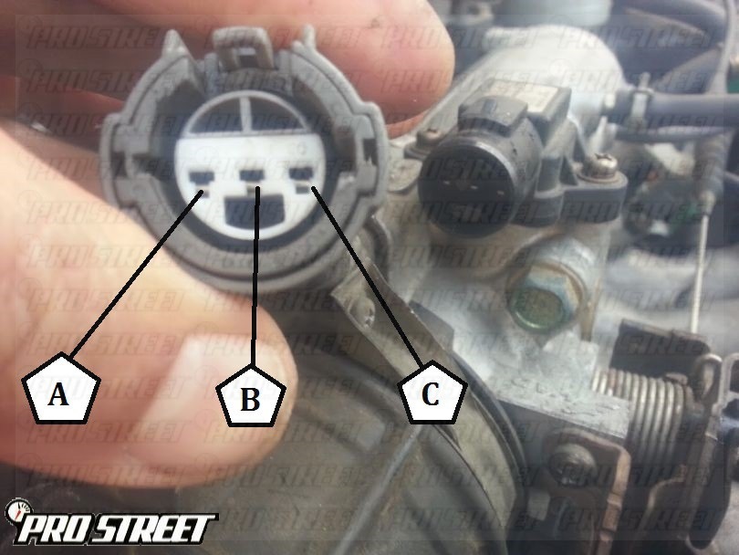
When dealing with vehicle electrical systems, understanding the Map Sensor Wiring Diagram is crucial. The Map Sensor Wiring Diagram provides a visual representation of the connections between the map sensor and the rest of the vehicle’s electrical system, helping mechanics diagnose and troubleshoot issues effectively. By following the wiring diagram, mechanics can identify faulty connections, broken wires, or other issues that may be causing problems with the map sensor.
Importance of Map Sensor Wiring Diagram
- Ensures proper connection of the map sensor to the vehicle’s electrical system
- Aids in diagnosing electrical issues related to the map sensor
- Helps in understanding the flow of electricity within the system
Reading and Interpreting Map Sensor Wiring Diagram
Reading and interpreting a Map Sensor Wiring Diagram may seem daunting at first, but with a little guidance, it becomes much easier. Here are some tips to help you navigate through the diagram effectively:
- Start by identifying the key components on the diagram, such as the map sensor, connectors, and wires.
- Follow the lines on the diagram to trace the connections between different components.
- Pay attention to the color codes and labels on the diagram to understand the function of each wire.
- Refer to the vehicle’s service manual for any specific information related to the map sensor wiring diagram.
Using Map Sensor Wiring Diagram for Troubleshooting
Map Sensor Wiring Diagrams are invaluable tools for troubleshooting electrical problems in vehicles. By following the diagram, mechanics can pinpoint the exact location of a faulty connection or wire, making repairs more efficient. Here’s how Map Sensor Wiring Diagrams can be used for troubleshooting:
- Identifying loose or disconnected wires that may be affecting the map sensor’s performance.
- Checking for short circuits or damaged wires that could be causing electrical issues.
- Testing the continuity of wires to ensure proper connection between components.
Safety Tips for Working with Map Sensor Wiring Diagram
When working with Map Sensor Wiring Diagrams or any vehicle electrical system, safety should always be a top priority. Here are some essential safety tips to keep in mind:
- Always disconnect the vehicle’s battery before working on any electrical components.
- Use insulated tools to prevent electric shocks or short circuits.
- Avoid touching exposed wires or terminals while the electrical system is powered.
- Double-check your work and ensure all connections are secure before reassembling the system.
Map Sensor Wiring Diagram
Map Sensor Wiring Diagram

Map Sensor Wiring Diagram

Map Sensor Wiring Diagram
DTC P0108 – How To Service Acura Integra MAP Sensor

[DIAGRAM] Gm Map Sensor Wiring Diagram – MYDIAGRAM.ONLINE
![Map Sensor Wiring Diagram [DIAGRAM] Gm Map Sensor Wiring Diagram - MYDIAGRAM.ONLINE](https://i1.wp.com/wiringall.com/image/wiring-diagram-2011-hyundai-sonata-map-sensor-connector-7.jpg)
Wiring for AEM map sensor and AIT | Ford Mustang Forums
Aem Map Sensor Wiring

bosch map sensor pinout – Wiring Digital and Schematic
