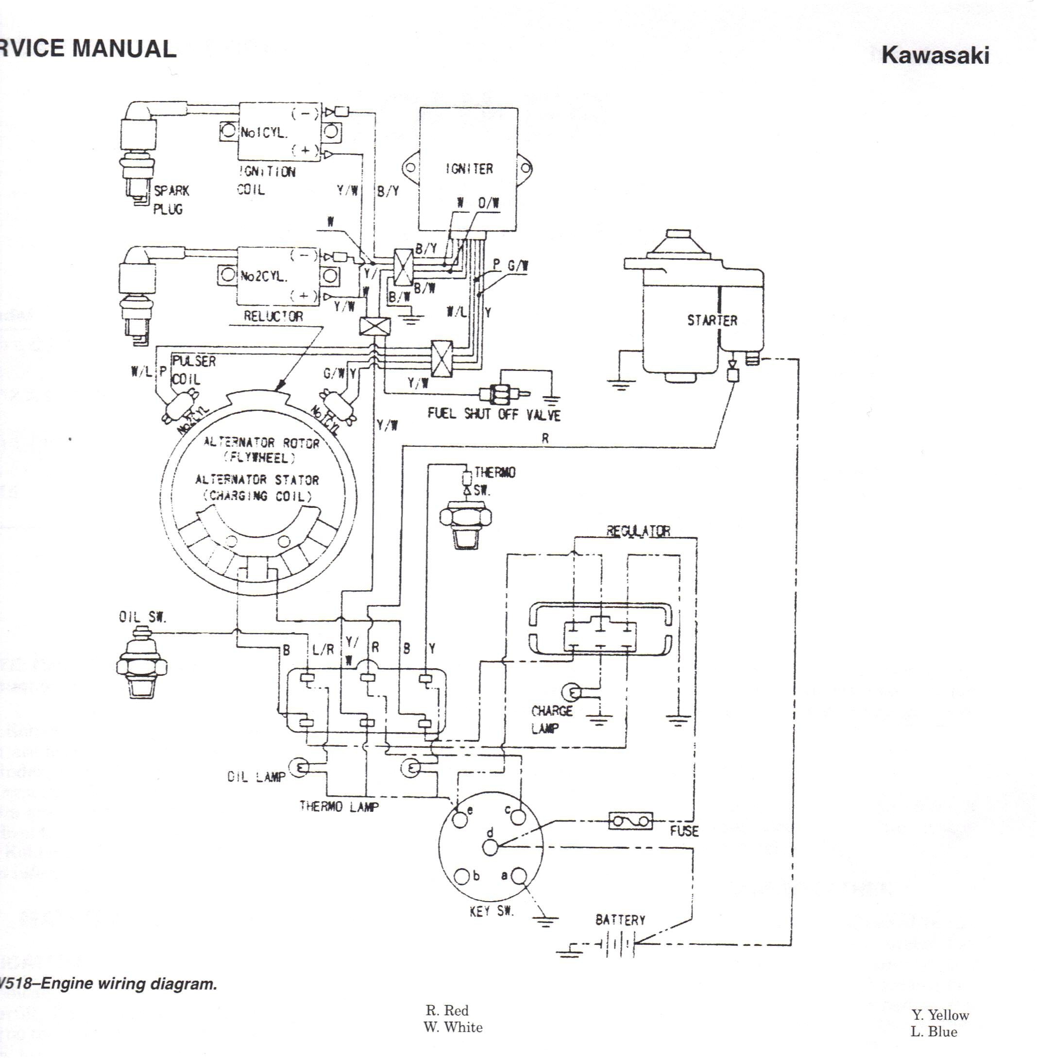
Welcome to this informative article about John Deere L110 Wiring Diagram. Understanding the wiring diagram for your John Deere L110 is crucial for maintaining and troubleshooting the electrical system of your equipment efficiently.
Why John Deere L110 Wiring Diagrams are Essential
Wiring diagrams for the John Deere L110 provide a visual representation of the electrical system of the equipment. They are essential for:
- Identifying the wiring connections
- Understanding the circuit layout
- Troubleshooting electrical issues
How to Read and Interpret John Deere L110 Wiring Diagram
Reading and interpreting the wiring diagram for your John Deere L110 can seem daunting at first, but with the right approach, it becomes a valuable tool. Here are some tips:
- Start by familiarizing yourself with the symbols and color codes used in the diagram
- Follow the wiring paths and connections from one component to another
- Refer to the legend or key to understand what each symbol represents
Using John Deere L110 Wiring Diagram for Troubleshooting
When faced with electrical problems in your John Deere L110, the wiring diagram can be your best friend. Here’s how you can use it effectively:
- Locate the component or circuit that is malfunctioning on the diagram
- Trace the wiring to identify any loose connections or damaged wires
- Check for continuity using a multimeter to determine if there is a break in the circuit
Importance of Safety
Working with electrical systems can be dangerous if proper precautions are not taken. Here are some safety tips to keep in mind when using wiring diagrams:
- Always disconnect the power source before working on the electrical system
- Use insulated tools to avoid electric shock
- Avoid working in wet or damp conditions to prevent short circuits
John Deere L110 Wiring Diagram
John Deere L110 Electrical Schematic – Wiring Diagram

John Deere L110 Electrical Schematic – Wiring Diagram
John Deere L110 Electrical Schematic – Wiring Diagram

Wiring Diagram For John Deere L110 – Wiring Boards
Wiring Diagram John Deere L110 Series Ii – Olive Wiring
John Deere L110 Wiring Diagram – General Wiring Diagram

John Deere L110 Wiring Diagram – Wiring Site Resource

John Deere L110 Electrical Schematic – Wiring Diagram
