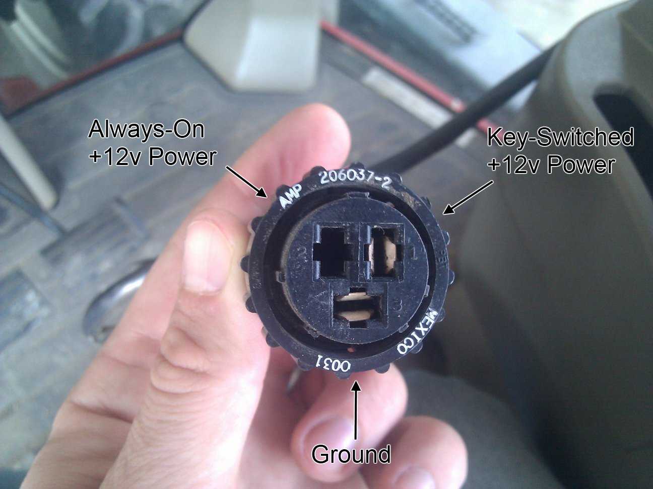
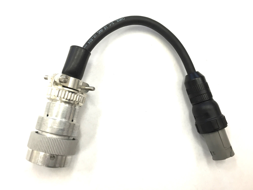
Are you in need of a comprehensive guide on John Deere 3 Pin Power Plug Wiring Diagram? Look no further, as we delve into the intricacies of this essential tool for any mechanic or technician working with John Deere equipment.
Why are John Deere 3 Pin Power Plug Wiring Diagram essential?
John Deere 3 Pin Power Plug Wiring Diagrams are crucial for understanding the electrical systems of John Deere equipment. They provide a detailed layout of the wiring connections, allowing technicians to troubleshoot and repair electrical issues effectively. Without these diagrams, diagnosing problems and making repairs would be significantly more challenging and time-consuming.
How to read and interpret John Deere 3 Pin Power Plug Wiring Diagram
When looking at a John Deere 3 Pin Power Plug Wiring Diagram, it’s important to understand the symbols and color codes used. Each wire is represented by a specific color, and various symbols indicate different components or connections. By familiarizing yourself with these elements, you can easily trace the wiring and identify any issues or discrepancies.
Using John Deere 3 Pin Power Plug Wiring Diagram for troubleshooting
John Deere 3 Pin Power Plug Wiring Diagrams are invaluable tools for troubleshooting electrical problems. By following the wiring diagram and tracing the connections, technicians can pinpoint the source of a malfunction and make the necessary repairs. This saves time and ensures that the problem is addressed correctly the first time.
Importance of safety when working with electrical systems
- Always disconnect the power source before working on any electrical system.
- Use insulated tools to prevent electrical shock.
- Avoid working in wet or damp conditions to reduce the risk of electrocution.
- Double-check your work and ensure all connections are secure before restoring power.
By following these safety tips and best practices, you can work confidently with John Deere 3 Pin Power Plug Wiring Diagrams and ensure a safe and successful repair process.
John Deere 3 Pin Power Plug Wiring Diagram
John Deere 3 Pin Power Plug Wiring Diagram

Complete Wiring Guide: John Deere 3-Pin Power Plug Diagram

john deere 3 pin power plug wiring diagram – ScotHarmonie

3 pin wiring harness plug connector convenience outlet for JOHN DEERE

john deere 3 pin power plug wiring diagram – ScotHarmonie
John Deere 3 Pin Power Plug Wiring Diagram – Wiringarc

Power, 3-pin AMP | Lefebure

John Deere 3 Pin Power Plug Wiring Diagram
