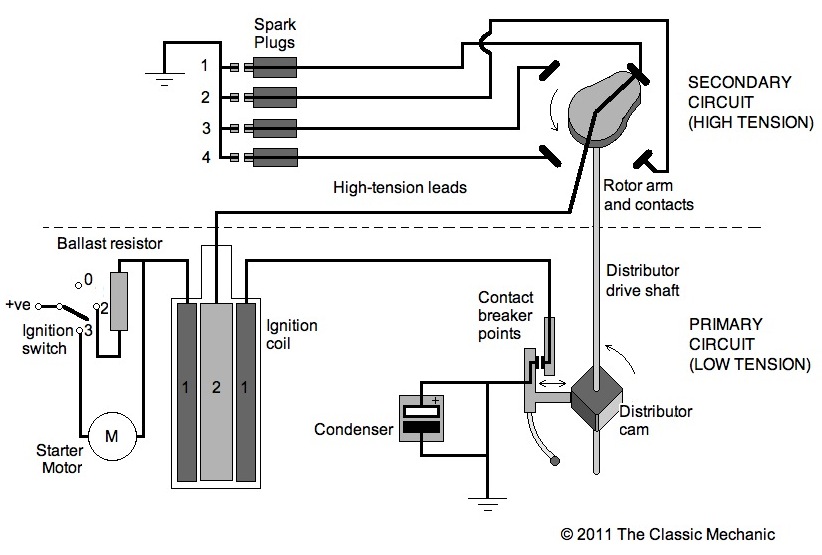
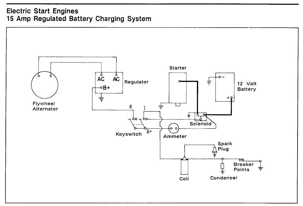
Ignition Coil Condenser Wiring Diagrams are essential tools for mechanics and DIY enthusiasts who need to understand the electrical connections in a vehicle’s ignition system. These diagrams show the wiring configuration of the ignition coil and condenser, helping users identify the different components and their connections.
Why Ignition Coil Condenser Wiring Diagrams are essential
Understanding the wiring diagram for the ignition coil and condenser is crucial for several reasons:
- Helps in diagnosing and troubleshooting electrical issues
- Ensures proper installation of components
- Aids in understanding the overall ignition system
How to read and interpret Ignition Coil Condenser Wiring Diagrams
When looking at an ignition coil condenser wiring diagram, it’s important to pay attention to the following:
- Color codes for wires
- Connection points for each component
- Direction of current flow
Using Ignition Coil Condenser Wiring Diagrams for troubleshooting
Ignition coil condenser wiring diagrams can be incredibly helpful when troubleshooting electrical problems. By following the diagram, you can:
- Identify faulty connections
- Check for continuity in wires
- Verify proper grounding
Safety tips when working with Ignition Coil Condenser Wiring Diagrams
When working with electrical systems and using wiring diagrams, it’s essential to follow these safety tips:
- Always disconnect the battery before working on the ignition system
- Use insulated tools to prevent electric shock
- Avoid working on the system in wet conditions
- Double-check all connections before re-energizing the system
Ignition Coil Condenser Wiring Diagram
The Classic Mechanic: Points/Condenser Ignition Explained

Understanding Your Battery Ignition System on your Kohler K Series

Ignition Coil Condenser Wiring Diagram

The Ultimate Guide to Understanding Ignition Coil Condenser Wiring Diagrams

A Complete Guide: Ignition Coil Condenser Wiring Diagram Explained

Ignition Coil Wiring Diagram Manual
Ignition Coil Schematic Diagram

Briggs And Stratton Points And Condenser Wiring Diagram
