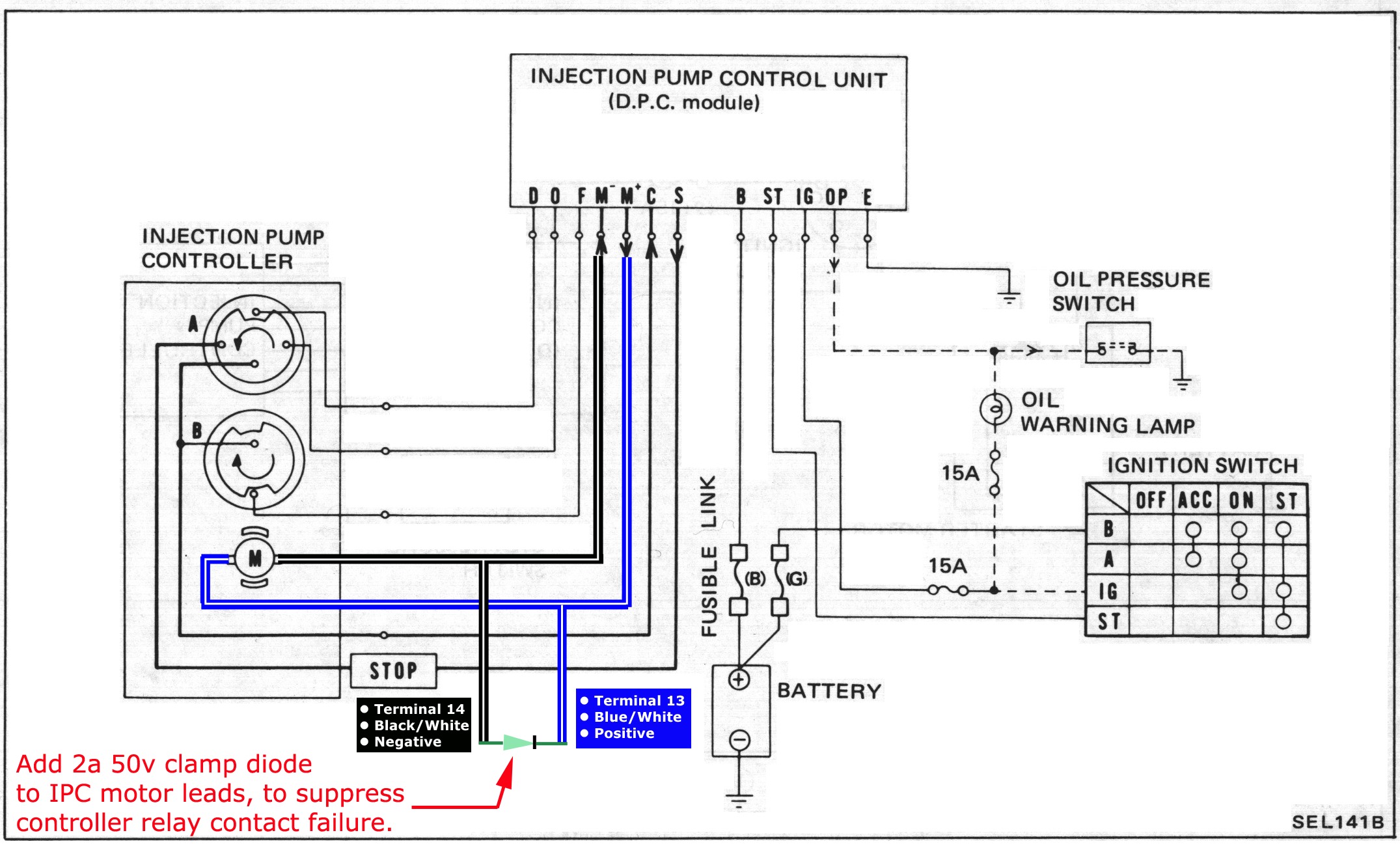
When it comes to understanding the intricate wiring of electrical systems in various devices, the Icm517 Wiring Diagram plays a crucial role. This diagram provides a detailed illustration of the electrical connections within a system, helping technicians and DIY enthusiasts to navigate the complex network of wires effectively.
Importance of Icm517 Wiring Diagram
- Helps in understanding the electrical connections in a system
- Aids in troubleshooting electrical issues
- Ensures proper installation and maintenance of electrical components
- Provides a visual representation of the wiring layout
Reading and Interpreting Icm517 Wiring Diagram
Reading and interpreting an Icm517 Wiring Diagram requires a basic understanding of electrical symbols and circuitry. The diagram typically consists of lines, symbols, and labels that represent various components and connections within the system. Here are some tips on how to effectively read and interpret the diagram:
- Start by identifying the main components of the system, such as the power source, switches, and loads.
- Follow the lines and connections to trace the path of electrical current flow.
- Refer to the legend or key provided on the diagram to understand the meaning of different symbols and labels.
- Pay attention to the color-coding of wires to differentiate between positive, negative, and ground connections.
Using Icm517 Wiring Diagram for Troubleshooting
When faced with electrical problems in a system, the Icm517 Wiring Diagram can be a valuable tool for troubleshooting. By following the wiring diagram and tracing the connections, technicians can pinpoint the source of the issue and make the necessary repairs or replacements. Here are some ways in which the diagram can be used for troubleshooting:
- Identifying faulty components or connections
- Checking for continuity and proper voltage levels
- Verifying proper grounding and insulation of wires
- Locating short circuits or open circuits within the system
It is important to exercise caution and follow safety protocols when working with electrical systems and using wiring diagrams. Here are some safety tips and best practices to keep in mind:
- Always turn off the power supply before working on any electrical system.
- Use insulated tools and equipment to prevent electrical shocks.
- Avoid working in wet or damp conditions to prevent electric shock hazards.
- Double-check all connections and wiring before restoring power to the system.
Icm517 Wiring Diagram
ICM517 S P D | Manualzz

24+ Icm517 Surge Protector Wiring Diagram Pictures – shuriken-mod

ICM517 | ICM Controls

ICM517 | ICM Controls

Wiring Diagram For Surge Protector

24+ Icm517 Surge Protector Wiring Diagram Pictures – shuriken-mod

ICM517 – Modern Electrical Supplies Ltd

* DPC MODULE & INJECTION PUMP CONTROLLER * – Page 2 – NissanDiesel Forums
