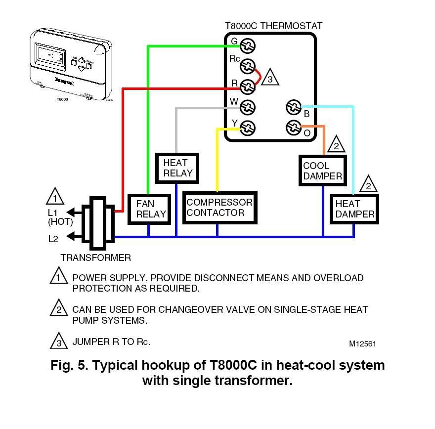
Are you looking to understand how Hvac Wiring Diagram Thermostat work? This article will provide you with a comprehensive guide on interpreting and using these diagrams effectively.
Why Hvac Wiring Diagram Thermostat are Essential
Hvac wiring diagrams for thermostats are essential for understanding the electrical connections and circuits in heating, ventilation, and air conditioning systems. They provide a visual representation of the wiring layout, helping technicians and homeowners troubleshoot issues, make repairs, and install new components accurately.
Reading and Interpreting Hvac Wiring Diagram Thermostat
- Start by familiarizing yourself with the symbols and color codes used in the diagram.
- Identify the components, such as the thermostat, air handler, condenser unit, and power source.
- Follow the lines to trace the path of electrical connections between the components.
- Pay attention to labels and wiring labels to ensure proper installation and troubleshooting.
Using Hvac Wiring Diagram Thermostat for Troubleshooting
When facing electrical problems in your HVAC system, refer to the wiring diagram to identify potential issues:
- Check for loose connections or damaged wires indicated in the diagram.
- Use a multimeter to test for continuity and voltage at various points in the circuit.
- Compare the actual wiring with the diagram to spot any discrepancies that could be causing the problem.
Importance of Safety and Best Practices
Working with electrical systems can be hazardous, so it’s crucial to follow safety precautions:
- Always turn off power to the HVAC system before attempting any repairs or modifications.
- Wear appropriate protective gear, such as gloves and safety glasses, to prevent electrical shocks.
- Consult a professional if you are unsure about reading or working with wiring diagrams.
Hvac Wiring Diagram Thermostat
Simple Thermostat Wiring Guide (2,3,4,5,6,7,8 Wires Color Code)

Wiring Diagram For Ac Unit Thermostat

Everything You Need to Know About Your HVAC Thermostat Wiring

Thermostat Wiring Diagram Honeywell

Wiring A Honeywell Thermostat With 4 Wires

How to Read Wiring Diagrams in HVAC Systems – MEP Academy

Thermostat Wiring Explained | Thermostat wiring, Hvac thermostat
