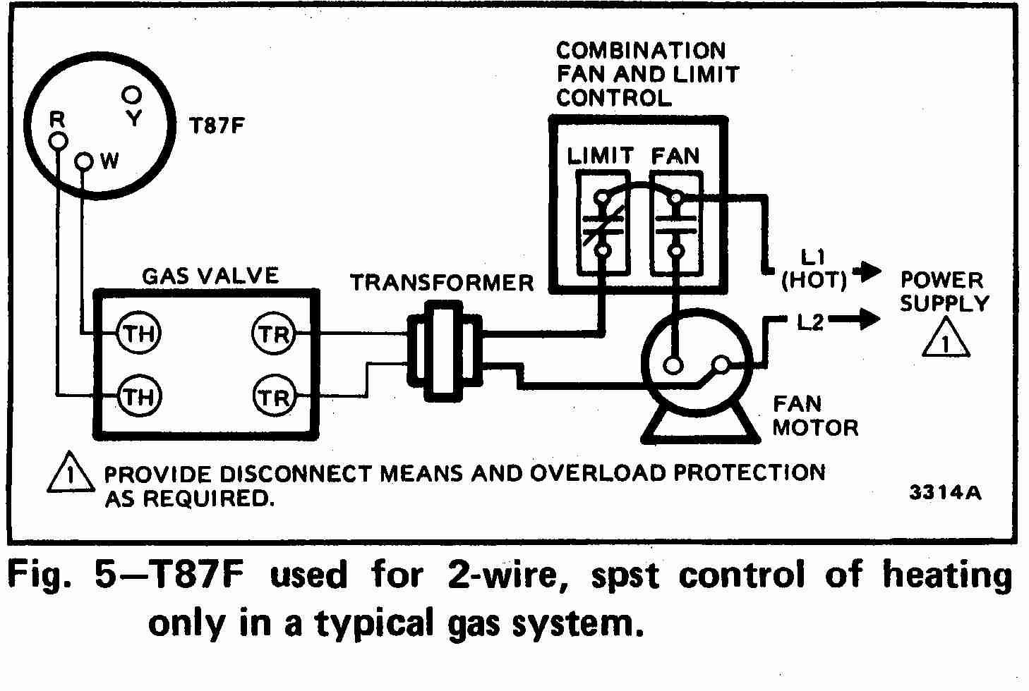
Are you looking for a reliable guide on Honeywell Zone Valve Wiring Diagram? Look no further! Understanding how to read and interpret these diagrams is essential for anyone working with heating systems. Let’s dive into the world of Honeywell Zone Valve Wiring Diagrams.
Why are Honeywell Zone Valve Wiring Diagrams essential?
Honeywell Zone Valve Wiring Diagrams are crucial for accurately wiring and troubleshooting heating systems. These diagrams provide a visual representation of the electrical connections within the zone valve, helping you ensure proper installation and functionality.
- Ensure correct wiring of zone valves
- Troubleshoot electrical issues efficiently
- Prevent damage to the heating system
How to read and interpret Honeywell Zone Valve Wiring Diagrams effectively
Reading and interpreting Honeywell Zone Valve Wiring Diagrams may seem daunting at first, but with a few key tips, you’ll be a pro in no time.
- Identify the components of the diagram
- Understand the symbols and colors used
- Follow the wiring paths carefully
Using Honeywell Zone Valve Wiring Diagrams for troubleshooting
When faced with electrical problems in your heating system, Honeywell Zone Valve Wiring Diagrams can be your best friend. By understanding these diagrams, you can pinpoint issues and take the necessary steps to resolve them.
- Locate the problem area on the diagram
- Check for loose connections or damaged wires
- Refer to the diagram for proper troubleshooting steps
Safety should always be a top priority when working with electrical systems and wiring diagrams. Here are some important safety tips to keep in mind:
- Turn off power before starting any work
- Use insulated tools to avoid electric shocks
- Double-check all connections before powering up the system
Honeywell Zone Valve Wiring Diagram
Honeywell V8043 Zone Valve Wiring Diagram – Wiring Diagram and Schematics

Honeywell Zone Valve Wiring to Taco Relay | Twinsprings Research Institute

Zone Valve Wiring Manuals Installation & Instructions: Guide to heating

Honeywell Zone Valve Wiring Diagram

Wiring Zone Valves

⭐Wiring Diagram For Zone Valves On Boiler⭐ – Mixedrace relationships

Zone Valve Wiring Installation & Instructions: Guide to heating system

Honeywell Zone Valve Wiring Diagram – Wiring Diagram
