Gy6 Stator Wiring Diagram
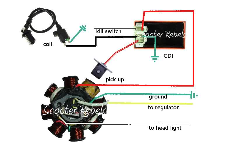
Gy6 Stator Wiring Diagram is a crucial tool for understanding the electrical connections in a Gy6 engine system. It provides a detailed layout of the wiring configuration, helping mechanics and enthusiasts easily identify and troubleshoot any electrical issues that may arise.
Importance of Gy6 Stator Wiring Diagram
- Ensures correct installation of electrical components
- Aids in diagnosing and fixing electrical problems
- Helps prevent damage to the electrical system
Reading and Interpreting Gy6 Stator Wiring Diagram
When looking at a Gy6 Stator Wiring Diagram, it’s important to understand the symbols and colors used to represent different components. Here are some tips to effectively read and interpret the diagram:
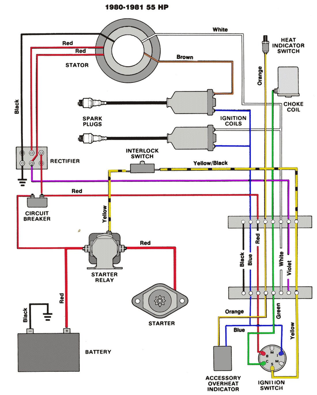
- Identify the key components such as stator, regulator, ignition coil, CDI, and other electrical parts
- Follow the color-coded lines to trace the electrical connections
- Pay attention to the arrows indicating the direction of current flow
Using Gy6 Stator Wiring Diagram for Troubleshooting
Gy6 Stator Wiring Diagrams are invaluable when troubleshooting electrical problems in a Gy6 engine system. By following the diagram, you can easily pinpoint the source of the issue and make the necessary repairs. Here’s how you can use the diagram effectively:
- Check for any loose or damaged connections indicated on the diagram
- Use a multimeter to test the continuity of the wires and components
- Refer to the diagram to ensure proper reassembly after troubleshooting
Safety Tips When Using Gy6 Stator Wiring Diagram
Working with electrical systems can be dangerous if proper precautions are not taken. Here are some safety tips to keep in mind when using Gy6 Stator Wiring Diagram:
- Always disconnect the battery before working on any electrical components
- Avoid working on the wiring system in wet or damp conditions
- Use insulated tools to prevent electric shock
- Double-check your work before reapplying power to the system
Gy6 Stator Wiring Diagram
Gy6 Stator Wiring Diagram

Gy6 Stator Wiring Diagram – Wiring Diagram Pictures

wiring diagram gy6 – Green Lab

Gy6 150cc Stator Wiring Diagram

Wiring Diagram For 150cc Gy6 Engine – Wiring Diagram

gy6 150cc dc cdi wiring diagram – Wiring Diagram and Schematics

Gy6 Stator Wiring Diagram – Wiring Diagram Pictures

Gy6 Stator Wiring Diagram : Yerf Dog 150cc Wiring Diagram Go Kart Buggy
