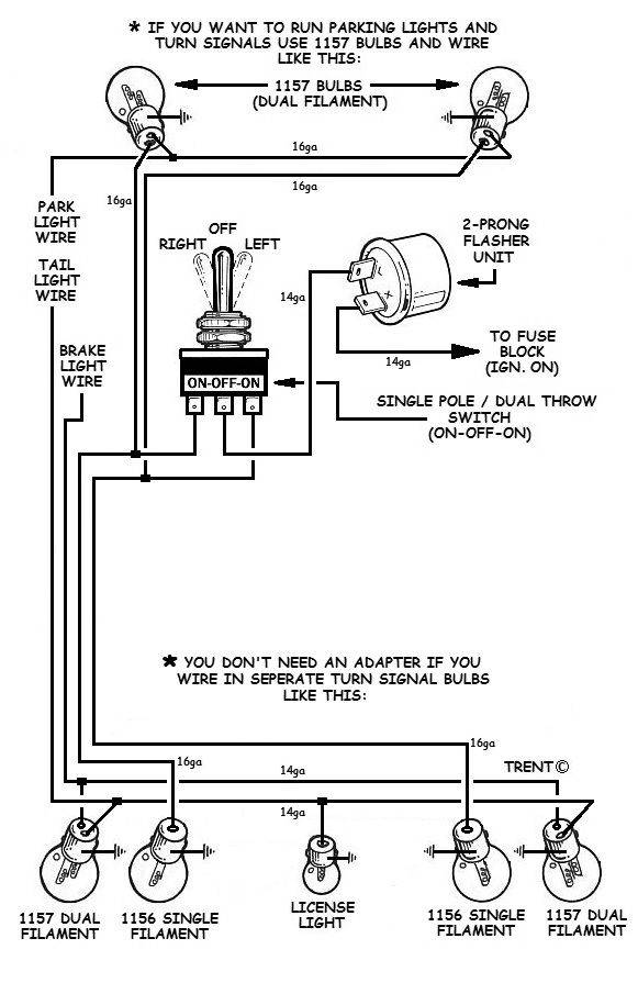
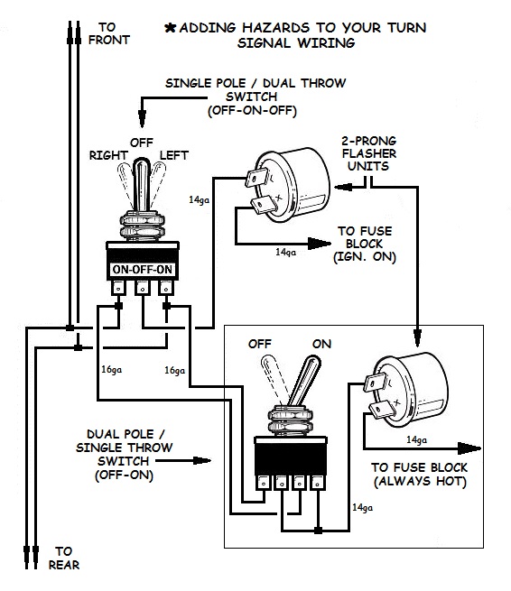
Gm Turn Signal Switch Wiring Diagram
When it comes to understanding the electrical system of your vehicle, having a clear and detailed Gm Turn Signal Switch Wiring Diagram is crucial. This diagram provides a visual representation of how the turn signal switch is wired in your GM vehicle, making it easier to troubleshoot any electrical issues that may arise.
Why Gm Turn Signal Switch Wiring Diagram are essential
- Helps in understanding the electrical system of your vehicle
- Aids in troubleshooting any electrical problems
- Ensures proper installation of new turn signal switches
- Provides a roadmap for conducting repairs and maintenance
How to read and interpret Gm Turn Signal Switch Wiring Diagram
Reading and interpreting a Gm Turn Signal Switch Wiring Diagram may seem daunting at first, but with a little practice, you can easily decipher the information it contains. Here are a few tips to help you make sense of the diagram:
- Pay attention to the color codes of the wires
- Identify the components connected to the turn signal switch
- Follow the flow of the wiring diagram to understand the circuit
Using Gm Turn Signal Switch Wiring Diagram for troubleshooting electrical problems
When faced with electrical issues in your vehicle, referring to the Gm Turn Signal Switch Wiring Diagram can be a lifesaver. This diagram allows you to pinpoint the source of the problem and take appropriate action to resolve it. Here’s how you can use the diagram for troubleshooting:
- Identify any loose or damaged connections
- Check for continuity in the circuit using a multimeter
- Refer to the diagram to understand the flow of electricity
Remember, safety should always be your top priority when working with electrical systems and wiring diagrams. Here are some safety tips to keep in mind:
- Always disconnect the battery before working on any electrical components
- Use insulated tools to avoid electric shocks
- Avoid working on the electrical system in wet conditions
- If you’re unsure about anything, seek professional help
Gm Turn Signal Switch Wiring Diagram
Gm Turn Signal Switch Wiring Diagram – Wiring Diagram

Gm Turn Signal Switch Wiring Diagram – Wiring Diagram
Gm Turn Signal Switch Wiring Diagram

Gm Turn Signal Wiring

Gm Turn Signal Switch Wiring Diagram – Wiring Draw And Schematic

Gm Turn Signal Switch Wiring Diagram – Wiring Draw And Schematic
Turn Signal Wiring Diagram 6 Wire

Gm Turn Signal Wiring Diagram
