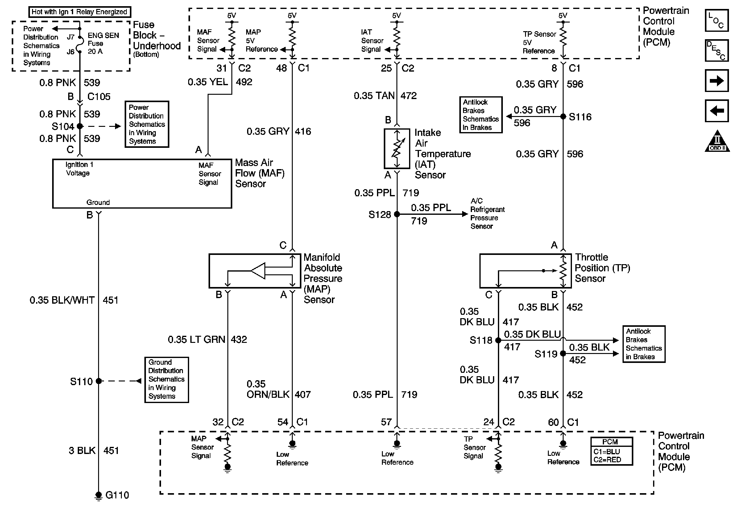
Are you looking for information on Gm Maf Sensor Wiring Diagram? Here, we will dive into the importance of these diagrams, how to read and interpret them effectively, and how they can be used for troubleshooting electrical problems.
Importance of Gm Maf Sensor Wiring Diagram
Gm Maf Sensor Wiring Diagrams are essential for several reasons:
- They provide a visual representation of the wiring connections for the MAF sensor, helping mechanics and technicians understand how the sensor is integrated into the vehicle’s electrical system.
- They help identify the different wires and their corresponding functions, making it easier to diagnose and repair any issues related to the MAF sensor.
- They serve as a guide for proper installation and maintenance of the MAF sensor, ensuring it functions correctly and efficiently.
Reading and Interpreting Gm Maf Sensor Wiring Diagram
When reading Gm Maf Sensor Wiring Diagrams, it is important to:
- Identify the components and connections within the diagram, such as power sources, grounds, sensors, and actuators.
- Understand the color-coding of the wires and the symbols used in the diagram to represent different electrical components.
- Follow the flow of the diagram to trace the path of electrical current and pinpoint any potential issues or malfunctions.
Using Gm Maf Sensor Wiring Diagram for Troubleshooting
Gm Maf Sensor Wiring Diagrams can be valuable tools for troubleshooting electrical problems, as they:
- Help identify faulty connections, damaged wires, or short circuits that may be causing issues with the MAF sensor.
- Assist in isolating specific components or circuits that need to be tested or replaced to resolve the problem effectively.
- Guide technicians in conducting systematic checks and tests to diagnose and repair electrical issues accurately.
Safety Tips for Working with Electrical Systems
When working with electrical systems and using wiring diagrams, it is crucial to prioritize safety:
- Always disconnect the vehicle’s battery before starting any electrical work to prevent accidents or injuries.
- Use insulated tools and wear appropriate safety gear, such as gloves and goggles, to protect yourself from electrical hazards.
- Avoid working on electrical systems in wet or damp conditions to reduce the risk of electric shock or damage to components.
Gm Maf Sensor Wiring Diagram
Maf Sensor Wiring Diagram 2003 Vibe

Maf Sensor Wiring Diagram Picture Schematic

Maf Sensor Wiring

2010 Chevy Silverado MAF Sensor Wiring Diagram | JustAnswer

02 5.3l Maf Wiring Diagram – Handicraftsism

3 wire maf to 5 wire maf conversion diagram? – LS1TECH

Gm Maf Sensor Wiring Diagram

Q&A: 5.3 Vortec Wiring Harness Diagram & GM MAF Sensor Pinout
