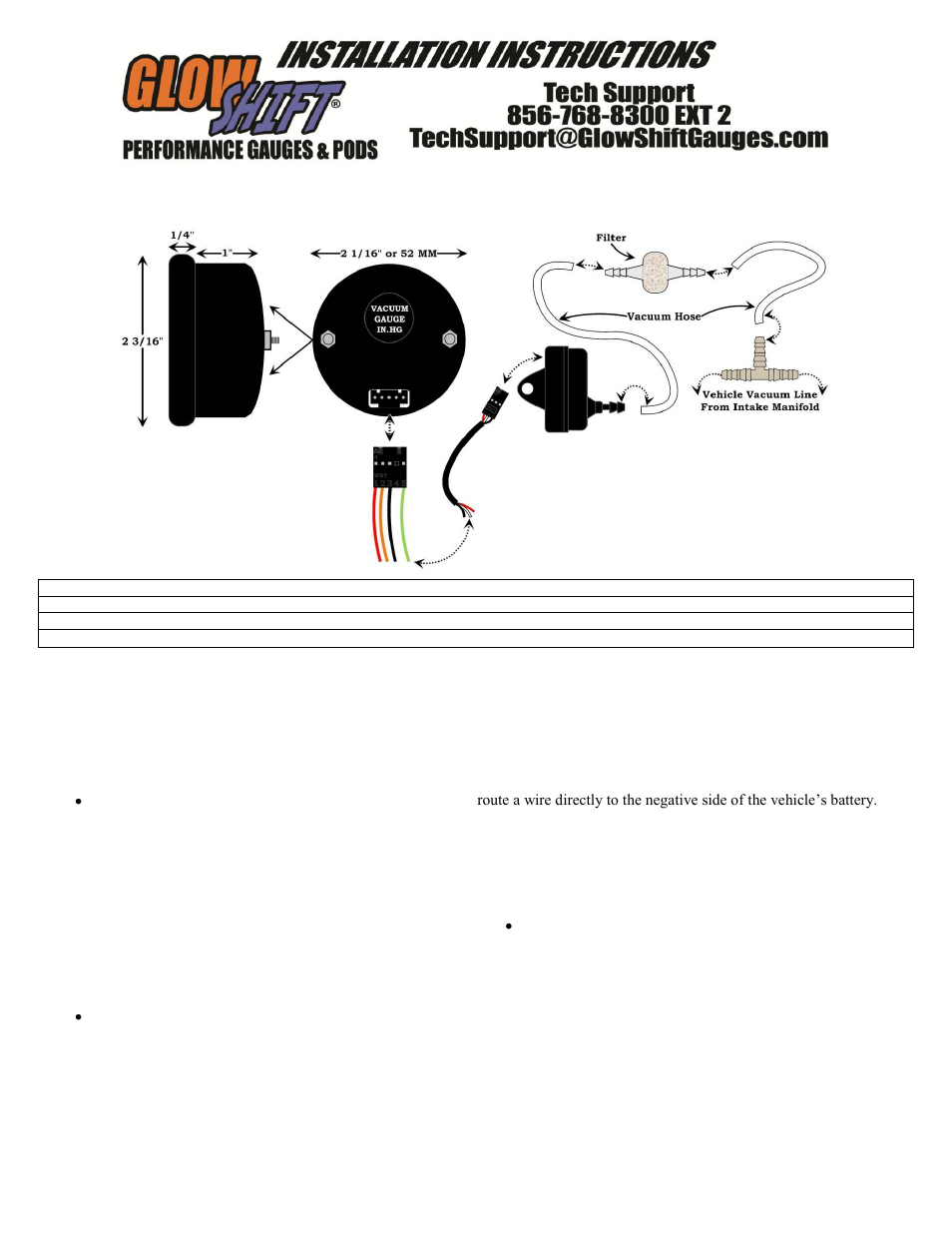
When it comes to installing aftermarket gauges in your vehicle, understanding the Glowshift Wiring Diagram is crucial. These diagrams provide a visual representation of how the gauges are wired into your vehicle’s electrical system, helping you to properly install and troubleshoot any issues that may arise.
Why Glowshift Wiring Diagrams are Essential
Glowshift Wiring Diagrams are essential for the following reasons:
- Helps you properly connect the gauges to the vehicle’s electrical system
- Ensures that the gauges function correctly
- Assists in troubleshooting any electrical issues that may occur
How to Read and Interpret Glowshift Wiring Diagrams
Reading and interpreting Glowshift Wiring Diagrams can be daunting for some, but with a little guidance, it can be a straightforward process. Here are some steps to help you effectively read and interpret the diagrams:
- Start by familiarizing yourself with the symbols and color codes used in the diagram
- Identify the components and their connections in the diagram
- Follow the wiring paths to understand how the gauges are connected to the vehicle’s electrical system
Using Glowshift Wiring Diagrams for Troubleshooting Electrical Problems
When faced with electrical issues in your vehicle, Glowshift Wiring Diagrams can be a valuable tool for troubleshooting. Here’s how you can use the diagrams effectively:
- Identify the specific circuit or component that is experiencing issues
- Follow the wiring diagram to trace the connections and identify any potential problems such as loose connections or damaged wires
- Refer to the diagram to make any necessary repairs or replacements to resolve the electrical problem
Importance of Safety When Working with Electrical Systems
Working with electrical systems can be dangerous if proper precautions are not taken. Here are some safety tips and best practices to keep in mind when using Glowshift Wiring Diagrams:
- Always disconnect the vehicle’s battery before working on the electrical system
- Avoid working on the electrical system in wet or damp conditions
- Use insulated tools to prevent electrical shocks
- Double-check your connections before turning on the vehicle to prevent any short circuits
Glowshift Wiring Diagram
Glowshift Fuel Pressure Gauge Wiring Diagram

Glowshift Oil Pressure Gauge Wiring – Wiring Diagram Pictures

Glowshift Fuel Pressure Gauge Wiring Diagram – Greenus

Glowshift Oil Pressure Gauge Wiring

Glowshift Fuel Pressure Gauge Wiring Diagram

Glowshift Volt Gauge Wiring Diagram – Wiring Diagram

GlowShift | Elite 10 Color Series BAR Boost Vacuum Gauge for Cars and

Glowshift Boost Gauge Wiring Diagram – Wiring Diagram Pictures
