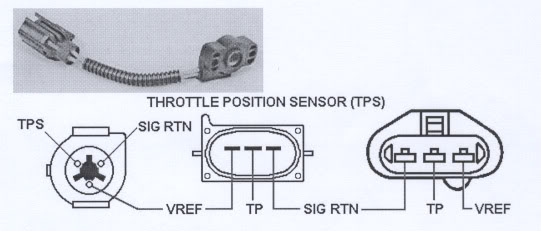
When it comes to understanding the intricacies of your Ford vehicle’s electrical system, the Ford Tps Wiring Diagram is an invaluable tool. This diagram provides a detailed map of the wiring connections for the Throttle Position Sensor (TPS) in your Ford vehicle, allowing you to easily pinpoint and troubleshoot any electrical issues that may arise.
Why are Ford Tps Wiring Diagrams essential?
- Help in identifying wire colors and connections
- Aid in diagnosing electrical problems
- Provide a roadmap for making repairs and modifications
- Essential for proper installation of new components
How to read and interpret Ford Tps Wiring Diagram effectively
When looking at a Ford Tps Wiring Diagram, it’s important to familiarize yourself with the key components and symbols used in the diagram. Pay close attention to wire colors, connector types, and pin assignments to ensure accurate interpretation.
Guidance on interpreting Ford Tps Wiring Diagram
- Refer to the legend or key for symbol definitions
- Follow the flow of the wiring diagram from input to output
- Identify the location of connectors and components
- Use color coding to match wires for proper connections
How Ford Tps Wiring Diagrams are used for troubleshooting electrical problems
By referencing the Ford Tps Wiring Diagram, you can pinpoint the source of electrical issues in your vehicle’s TPS system. Whether it’s a faulty connection, broken wire, or malfunctioning sensor, the diagram provides a roadmap for effective troubleshooting and repairs.
Importance of safety when working with electrical systems
- Always disconnect the battery before working on the electrical system
- Use insulated tools to avoid electrical shock
- Avoid working on electrical components in wet or damp conditions
- Double-check all connections before reapplying power
Ford Tps Wiring Diagram
Understanding Ford Throttle Position Sensor Wiring Diagrams – Wiring

Ford Tps Wiring Diagram

How Do I Wire My Car For An Older/Newer Style TPS? | Stinger

Ford Tps Wiring Diagram

Ford Throttle Position Sensor Wiring Diagram – parleyinspire

Ford Throttle Position Sensor Wiring Diagram – parleyinspire

ford throttle position sensor wiring diagram – CiarronAela
Ford Tps Wiring
