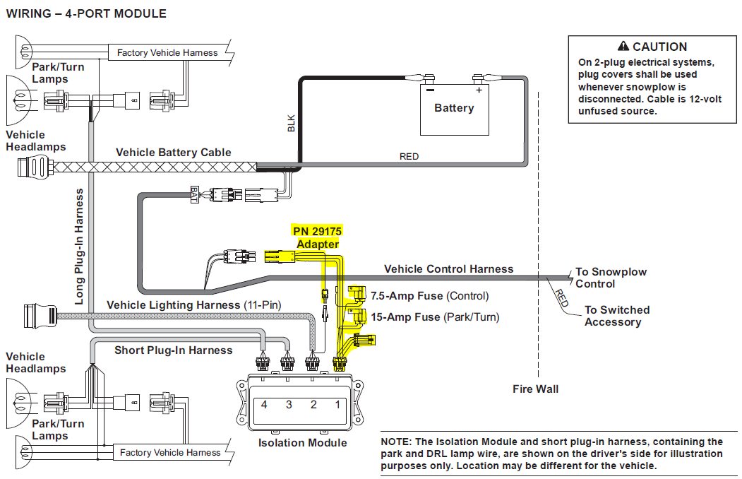
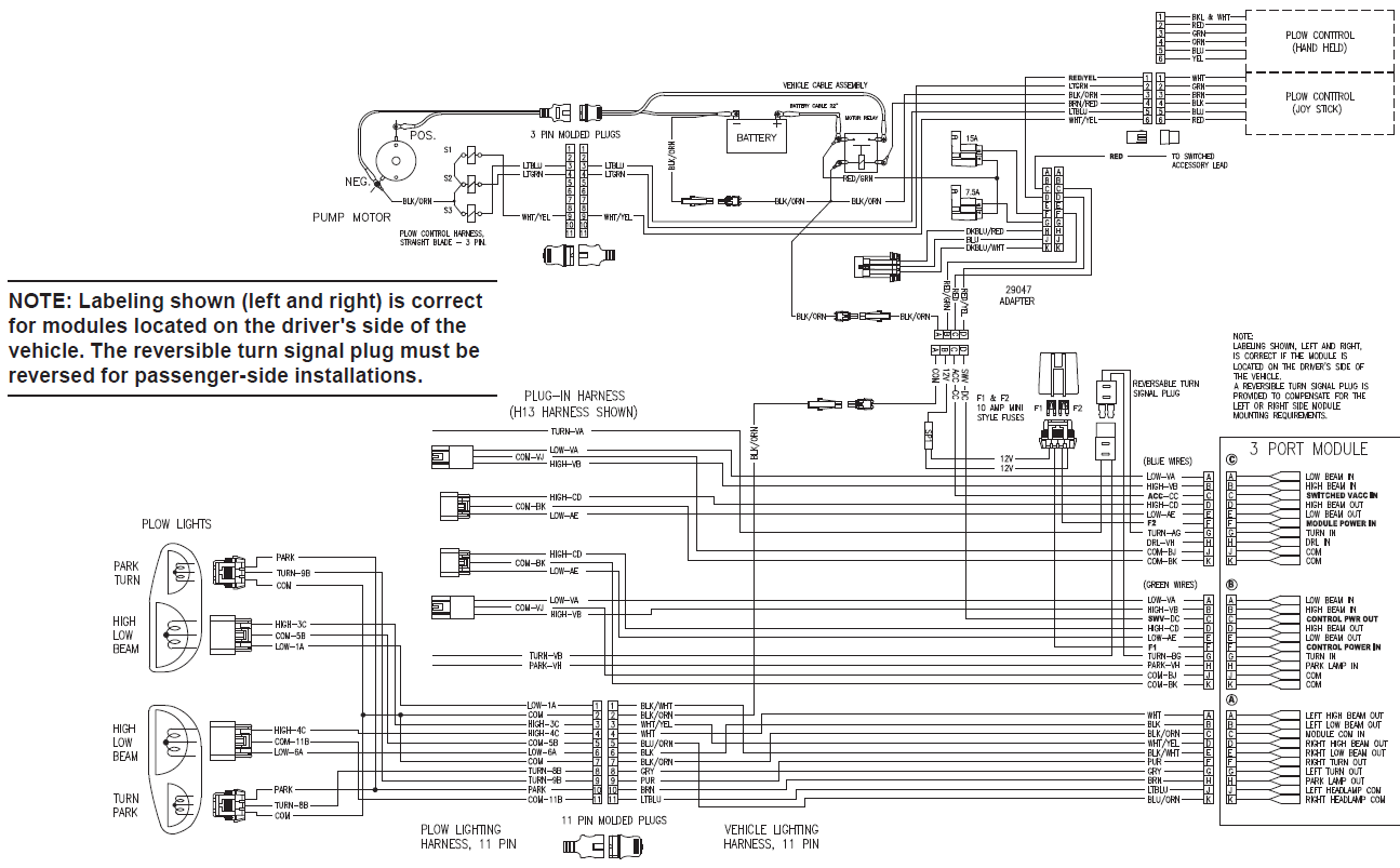
When working on electrical systems in vehicles, having a clear understanding of the wiring diagram is essential. In this article, we will explore the Fisher 4 Port Isolation Module Wiring Diagram and how it can help mechanics troubleshoot and repair electrical issues.
Why Fisher 4 Port Isolation Module Wiring Diagram Is Essential
The Fisher 4 Port Isolation Module Wiring Diagram is a crucial tool for anyone working on the electrical systems of a vehicle. It provides a visual representation of the wiring layout, connections, and components, making it easier to identify and understand how the system is configured.
- Helps in identifying connections
- Ensures proper installation of components
- Aids in diagnosing electrical issues
How to Read and Interpret Fisher 4 Port Isolation Module Wiring Diagram
Reading and interpreting a wiring diagram can seem daunting at first, but with practice, it becomes easier. Here are some tips to help you navigate a Fisher 4 Port Isolation Module Wiring Diagram effectively:
- Start by familiarizing yourself with the symbols and colors used in the diagram
- Follow the flow of the circuit from the power source to the components
- Pay attention to how the wires are connected and the direction of the current
Using Fisher 4 Port Isolation Module Wiring Diagram for Troubleshooting
When faced with electrical problems in a vehicle, the Fisher 4 Port Isolation Module Wiring Diagram can be a lifesaver. By following the diagram and tracing the connections, you can pinpoint the source of the issue and make the necessary repairs.
- Identify potential problem areas based on the wiring diagram
- Test connections and components to verify functionality
- Refer to the diagram to ensure correct reassembly after repairs
Importance of Safety
Working with electrical systems can be dangerous if proper precautions are not taken. When using wiring diagrams, it is crucial to prioritize safety to prevent accidents and injuries. Here are some safety tips to keep in mind:
- Always disconnect the power source before working on the electrical system
- Use insulated tools to avoid electrical shocks
- Avoid working on wet or damp surfaces to prevent electrical hazards
Fisher 4 Port Isolation Module Wiring Diagram
Understanding Fisher 4 Port Isolation Module Wiring Diagrams – Moo Wiring

Fisher 4 Port Isolation Module Wiring Diagram

Fisher Plow 4 Port Isolation Module Wiring Diagram For Your Needs

Fisher 4 Port Isolation Module Wiring Diagram – Easy Wiring

Fisher 4 Port Isolation Module Wiring Diagram – Easy Wiring

fisher 4 port isolation module wiring diagram – Laceist
marinah: [3+] Fisher 4 Port Isolation Module Wiring Diagram, Fisher 4
![Fisher 4 Port Isolation Module Wiring Diagram marinah: [3+] Fisher 4 Port Isolation Module Wiring Diagram, Fisher 4](https://i1.wp.com/www.mikrora.com/wp-content/uploads/2019/04/fisher_4_port_isolation_module_wiring_diagram_lovely_boss_plow_wiring_turn_signal_enthusiast_wiring_diagrams_e280a2_0.jpg)