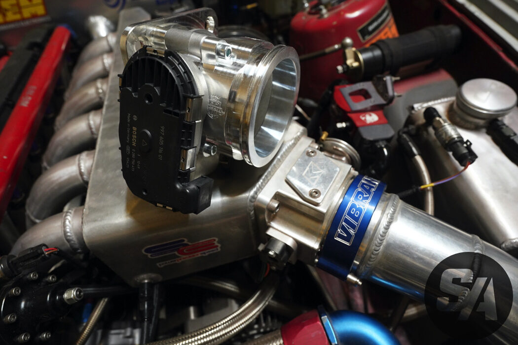
Drive By Wire Throttle Body Wiring Diagrams are essential tools for understanding the electrical connections and wiring configurations of the throttle body in a drive-by-wire system. These diagrams provide a visual representation of the wiring layout, wire colors, and connection points, making it easier to diagnose and troubleshoot electrical issues.
Why Drive By Wire Throttle Body Wiring Diagrams are essential:
- Helps identify the various components of the throttle body wiring system
- Aids in understanding the wiring connections and their functions
- Facilitates troubleshooting and diagnosing electrical problems
- Ensures proper installation and connection of wires
How to read and interpret Drive By Wire Throttle Body Wiring Diagrams effectively:
When looking at a wiring diagram for a drive-by-wire throttle body, it’s important to understand the symbols and color codes used. Each wire is represented by a specific color and label, indicating its function and connection point. By following the lines and connections on the diagram, you can trace the flow of electricity through the system and identify any potential issues.
Using Drive By Wire Throttle Body Wiring Diagrams for troubleshooting electrical problems:
Drive By Wire Throttle Body Wiring Diagrams are invaluable tools for troubleshooting electrical problems in a vehicle. By referencing the diagram, you can pinpoint the source of an issue, such as a faulty connection or damaged wire. This helps to expedite the repair process and ensure that the throttle body operates correctly.
Importance of safety when working with electrical systems:
- Always disconnect the battery before working on any electrical components
- Use insulated tools to prevent electrical shock
- Avoid working on electrical systems in wet or damp conditions
- Refer to the vehicle’s service manual for specific safety precautions
Drive By Wire Throttle Body Wiring Diagram
Bosch 82mm Drive By Wire Throttle Body – NZEFI

RX8 DBW throttle pinout – G4+ – Link Engine Management

Incredible Throttle Body Wiring Diagram References – blissinspire

350Z DBW Pedal and Throttle Body Pinout and Wiring

Drive By Wire Throttle Wiring Question – RX8Club.com

Drive By Wire Throttle Wiring
Drive-By-Wire Throttle Body Conversion Done Right! | Speed Academy

Gm Throttle Body Wiring Diagram
