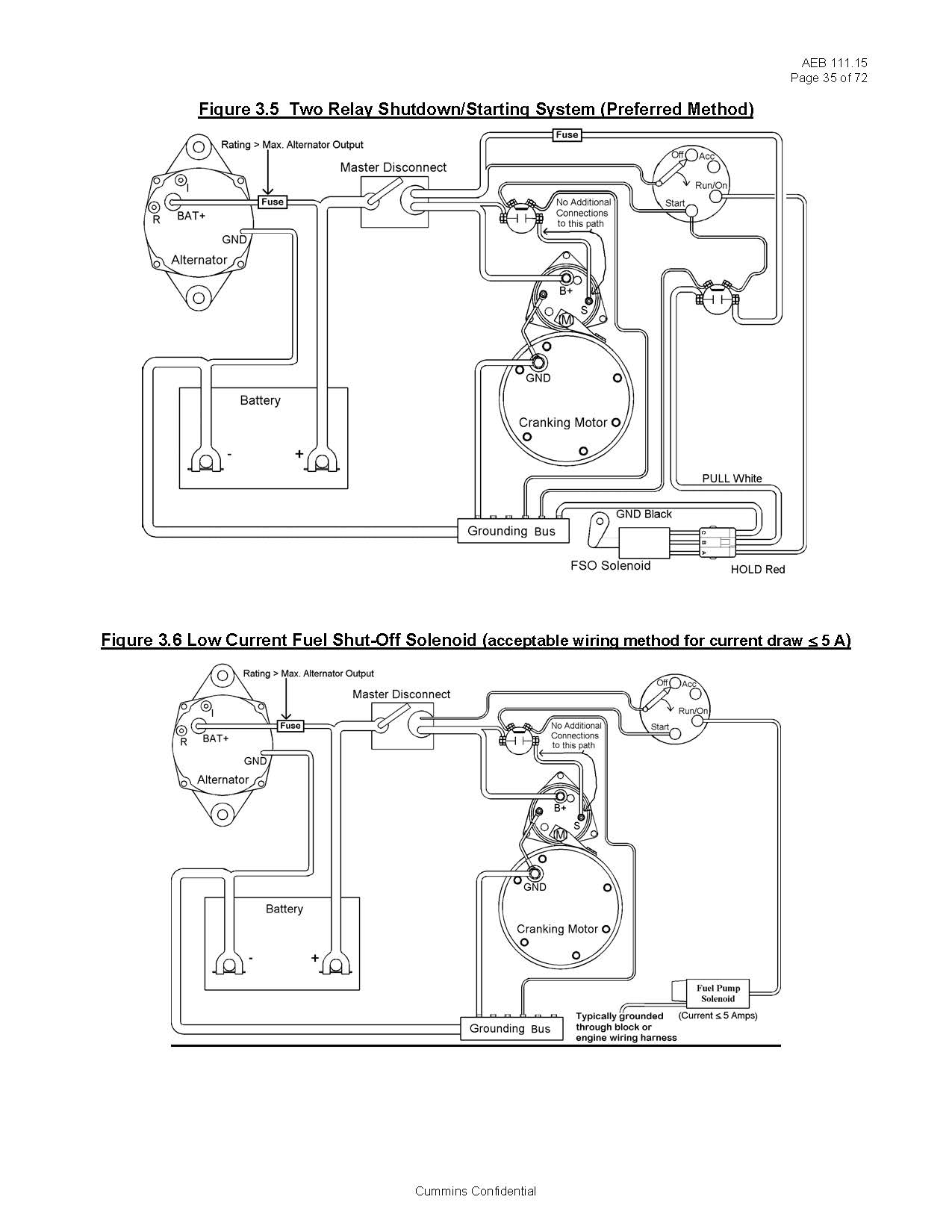
Diesel Fuel Shut Off Solenoid Wiring Diagram
When it comes to the operation of diesel engines, the Diesel Fuel Shut Off Solenoid plays a crucial role in controlling the fuel flow to the engine. Understanding the wiring diagram for this component is essential for proper maintenance and troubleshooting. In this article, we will explore the importance of Diesel Fuel Shut Off Solenoid Wiring Diagram and how to effectively interpret them.
Importance of Diesel Fuel Shut Off Solenoid Wiring Diagram
- Ensures proper installation of the solenoid
- Aids in troubleshooting electrical issues related to the solenoid
- Helps in understanding the wiring connections for the solenoid
Reading and Interpreting Diesel Fuel Shut Off Solenoid Wiring Diagram
When looking at a wiring diagram for a Diesel Fuel Shut Off Solenoid, it is important to pay attention to the symbols and color codes used. Each wire’s function and connection point should be clearly indicated for easy understanding. Here are some tips for effective interpretation:
- Identify the power source and ground connections
- Follow the wire paths to understand the circuit flow
- Note any fuses or relays in the circuit
Using Wiring Diagrams for Troubleshooting
When faced with electrical issues related to the Diesel Fuel Shut Off Solenoid, the wiring diagram can be a valuable tool for troubleshooting. By tracing the circuit and checking for continuity, you can pinpoint the source of the problem and make the necessary repairs. Here are some common troubleshooting steps:
- Check for loose or damaged connections
- Test the continuity of the wires using a multimeter
- Inspect the solenoid for any signs of wear or malfunction
It is important to always prioritize safety when working with electrical systems and wiring diagrams. Here are some safety tips to keep in mind:
- Always disconnect the power source before working on any electrical components
- Use insulated tools to prevent electric shock
- Avoid working on wet surfaces or in damp conditions
- Refer to the manufacturer’s guidelines for proper handling of electrical components
Diesel Fuel Shut Off Solenoid Wiring Diagram
2 Wire Fuel Shut Off Solenoid Wiring Diagram

Kubota Fuel Shut Off Solenoid Wiring Diagram

Basic Fuel Shutoff Solenoid and Starter Wiring Information – Seaboard

3 Wire Fuel Shut Off Solenoid Wiring Diagram – GREAT DIAGRAM

Fuel Shutoff Solenoid Wiring 101 – Seaboard Marine – Cummins Fuel Shut

3 Wire Fuel Shut Off Solenoid Wiring Diagram – GREAT DIAGRAM

3 Wire Fuel Shut Off Solenoid Wiring Diagram – GREAT DIAGRAM
Schematic 3 Wire Fuel Shut Off Solenoid Wiring Diagram – Wiring Service
