Introduction
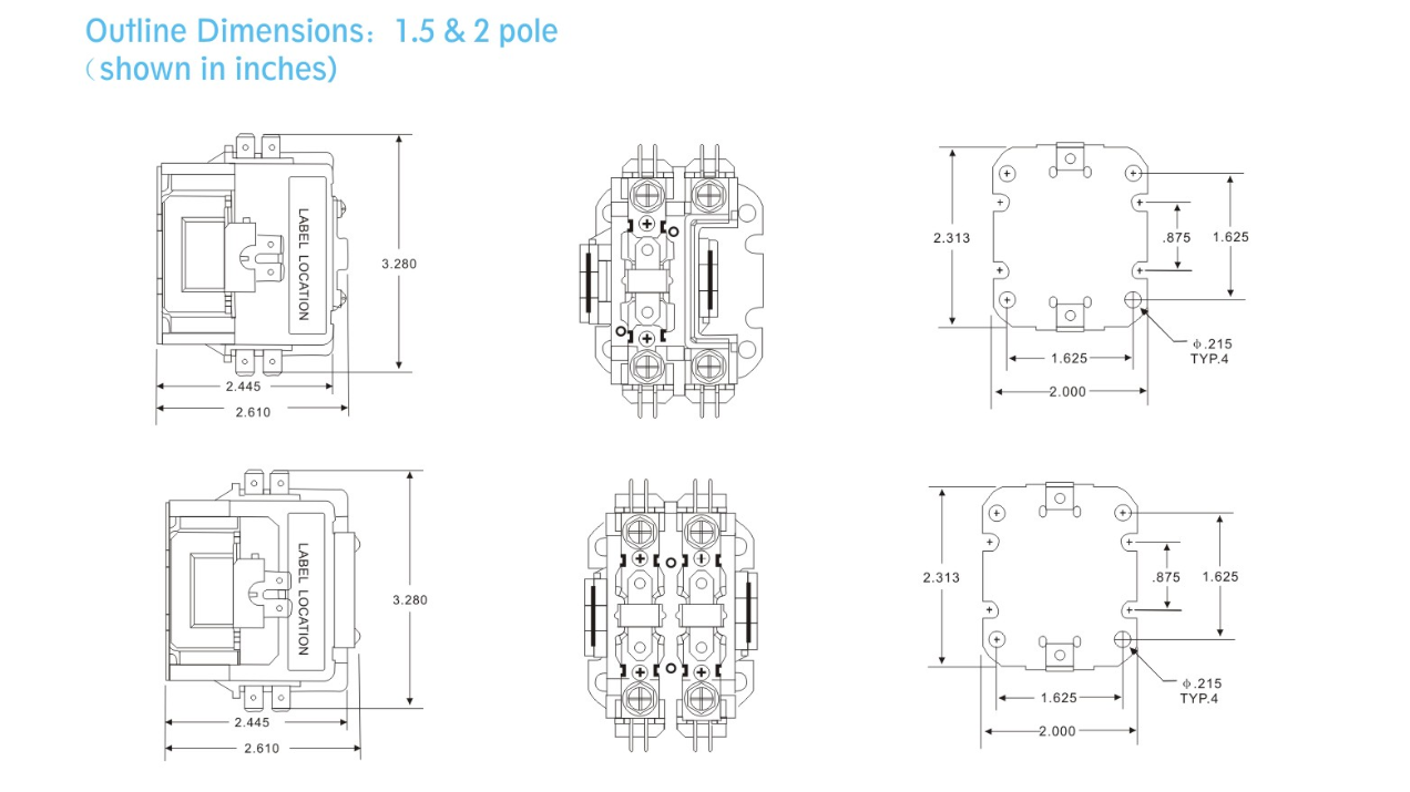
When it comes to electrical systems, understanding the wiring diagram for a definite purpose contactor is crucial. A definite purpose contactor wiring diagram provides a visual representation of how the contactor is wired, helping to ensure proper installation and functionality.
Why Definite Purpose Contactor Wiring Diagrams are Essential
Definite purpose contactor wiring diagrams are essential for several reasons:
- They provide a clear and organized layout of how the contactor is wired.
- They help to identify the different components of the contactor and their connections.
- They ensure that the contactor is installed correctly, preventing potential electrical issues.
How to Read and Interpret Definite Purpose Contactor Wiring Diagrams
Reading and interpreting a definite purpose contactor wiring diagram may seem daunting at first, but with some guidance, it becomes much easier:
- Start by understanding the symbols used in the wiring diagram, such as switches, relays, and connectors.
- Follow the lines to trace the connections between components and understand how they interact.
- Pay attention to the labeling of each component to ensure proper identification.
Using Definite Purpose Contactor Wiring Diagrams for Troubleshooting
Definite purpose contactor wiring diagrams can also be used for troubleshooting electrical problems:
- By following the wiring diagram, you can identify any faulty connections or components that may be causing issues.
- You can use the diagram to trace the flow of electricity and pinpoint the source of the problem.
- Having a clear understanding of the wiring diagram can help you efficiently troubleshoot and resolve electrical issues.
Importance of Safety
When working with electrical systems and using wiring diagrams, safety should always be the top priority:
- Ensure that the power is turned off before working on any electrical components.
- Use insulated tools to prevent electrical shocks.
- Double-check all connections and follow proper wiring practices to avoid short circuits or other hazards.
By following safety guidelines and utilizing definite purpose contactor wiring diagrams effectively, you can ensure a safe and successful electrical installation or troubleshooting process.
Definite Purpose Contactor Wiring Diagram
Two Pole Contactor Wiring Diagram Ac

How to Wire an Eaton Definite Purpose Contactor: A Step-by-Step Wiring

Three Phase Contactor Wiring Diagram. | Electrical Engineering Blog
How To Wire A 3 Pole Contactor

Two Pole Contactor Wiring Diagram Ac

How To Connect A Contactor Diagram – Wiring Draw And Schematic
30 Definite Purpose Contactor Wiring Diagram – Wire Diagram Source

Square D 8910 Dpa 43 Wiring Diagram – Art Mark
