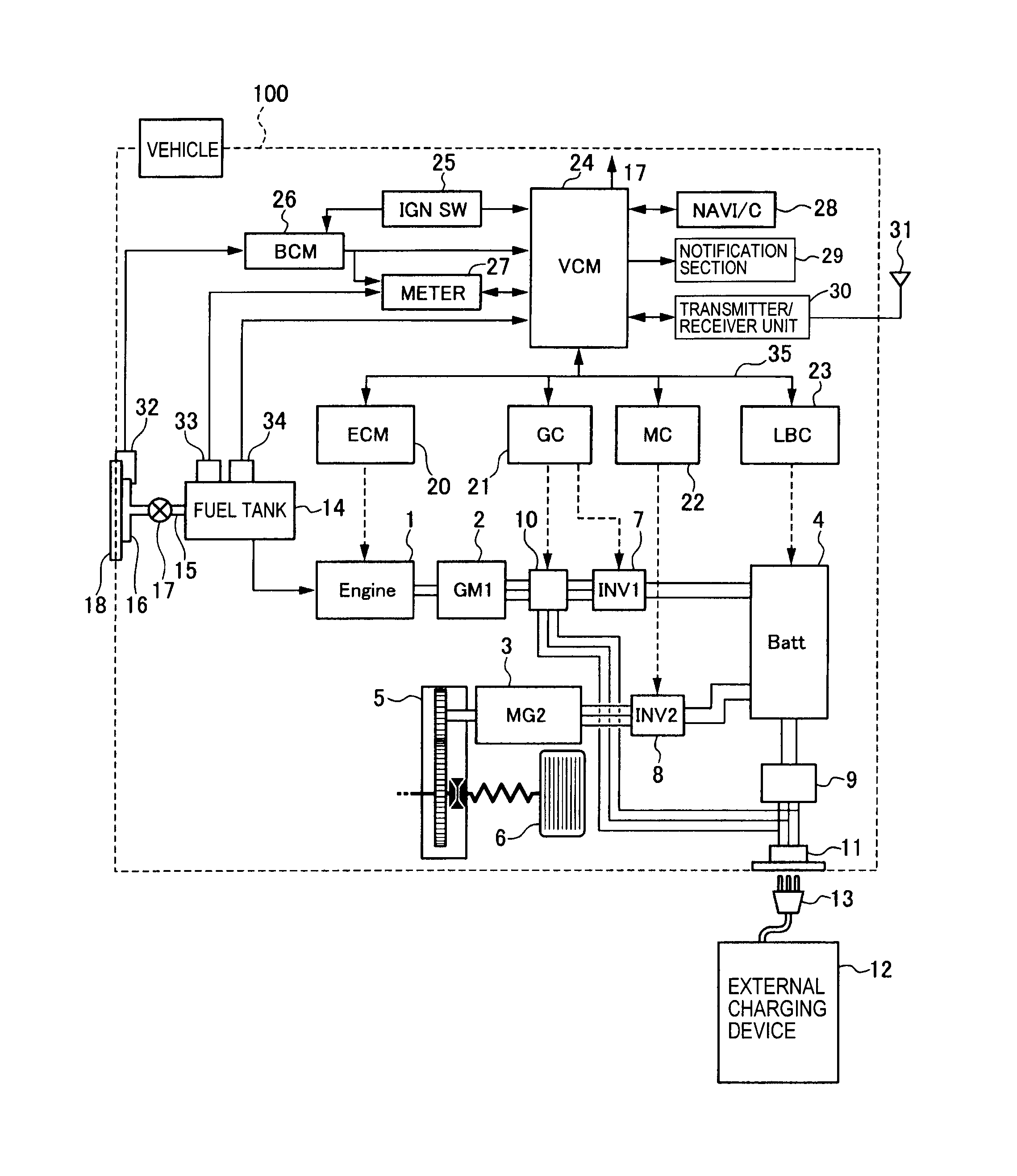
When it comes to understanding and troubleshooting electrical systems in vehicles, the Curtis 1204 Controller Wiring Diagram is an essential tool. This diagram provides a detailed illustration of the wiring connections and electrical components of the Curtis 1204 controller, helping mechanics and technicians diagnose and repair issues effectively.
Importance of Curtis 1204 Controller Wiring Diagram
- Helps identify the correct wiring connections for the controller
- Assists in troubleshooting electrical problems
- Ensures proper installation and operation of the controller
Reading and Interpreting Curtis 1204 Controller Wiring Diagram
Reading and interpreting a wiring diagram can seem daunting at first, but with some guidance, it becomes much easier. The key components of a Curtis 1204 Controller Wiring Diagram include:
- Color-coded wires for easy identification
- Symbols representing different electrical components
- Connections between components indicated by lines
Using Curtis 1204 Controller Wiring Diagram for Troubleshooting
When facing electrical problems in a vehicle’s system, the Curtis 1204 Controller Wiring Diagram can be a valuable resource. By following the wiring diagram, you can:
- Trace the path of electrical connections to locate faults
- Check for continuity and proper voltage at various points
- Identify potential issues with specific components
Safety Tips for Working with Electrical Systems
When working with electrical systems and using wiring diagrams, it is crucial to prioritize safety. Here are some safety tips and best practices to keep in mind:
- Always disconnect the vehicle’s battery before working on electrical systems
- Use insulated tools to prevent electric shocks
- Avoid working on electrical systems in wet or damp conditions
- If unsure about a wiring connection, consult a professional mechanic or electrician
Curtis 1204 Controller Wiring Diagram
Curtis 1204 Controller Wiring Diagram – Wiring Diagram Pictures

Curtis 1204 Controller Wiring Diagram – General Wiring Diagram

Curtis 1204 Controller Wiring Diagram – diagramwirings

1204 Curtis Controller Wiring Diagram | Wiring Library – Curtis

Curtis 1204 Controller Wiring Diagram

1204 Curtis Controller Wiring Diagram | Wiring Library – Curtis

Curtis 1204 Controller Wiring Diagram – Uploadish
