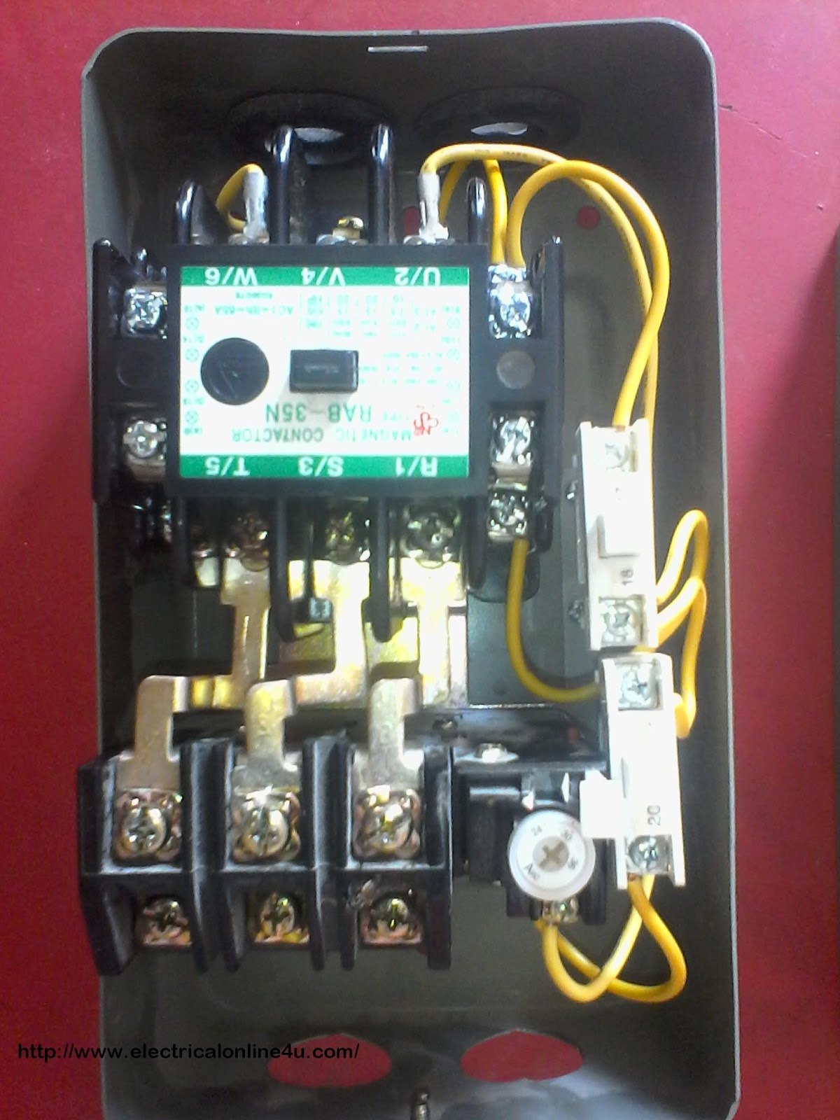
When it comes to electrical systems, understanding the ins and outs of contactor wiring diagrams is essential. A contactor wiring diagram is a detailed schematic that illustrates the connections between various components in an electrical circuit, specifically in relation to contactors. These diagrams are crucial for electricians, technicians, and DIY enthusiasts alike to properly install, troubleshoot, and maintain electrical systems.
Why are Contactor Wiring Diagrams Essential?
- Helps in understanding the circuit layout
- Aids in proper installation of contactors
- Facilitates troubleshooting and maintenance
- Ensures safety by preventing electrical hazards
How to Read and Interpret Contactor Wiring Diagrams
Contactor wiring diagrams may seem complex at first glance, but with a little practice, anyone can decipher them effectively. Here are some tips on how to read and interpret contactor wiring diagrams:
- Identify the symbols and components used in the diagram
- Follow the flow of the circuit from power source to load
- Pay attention to wire colors and connections
- Refer to the legend or key for any unfamiliar symbols
Using Contactor Wiring Diagrams for Troubleshooting
When faced with electrical problems, contactor wiring diagrams can be a valuable tool for troubleshooting. By following the wiring diagram and tracing the connections, technicians can pinpoint the source of the issue and make the necessary repairs. Common troubleshooting steps include:
- Checking for loose or damaged wires
- Testing the continuity of circuits using a multimeter
- Verifying proper voltage levels at various points in the circuit
Importance of Safety
Working with electrical systems can be dangerous if proper precautions are not taken. When using contactor wiring diagrams, it is crucial to prioritize safety to prevent accidents and injuries. Here are some safety tips and best practices to keep in mind:
- Always turn off the power before working on any electrical circuit
- Use insulated tools to avoid electric shocks
- Wear personal protective equipment, such as gloves and safety goggles
- Follow manufacturer instructions and local electrical codes
Contactor Wiring Diagram
How to Wire a Contactor: 8 Steps (with Pictures) – wikiHow

How To Connect A Contactor Diagram – Wiring Draw And Schematic
Single Phase 2 Pole Contactor Wiring Diagram

Single Phase Contactor Wiring Diagram A1 A2 | Electrical Wiring

How To Wire Contactor And Overload Relay – Contactor Wiring Diagram

Wiring A Contactor Diagram

Three Phase Contactor Wiring Diagram
240 Volt Contactor Wiring Diagram
