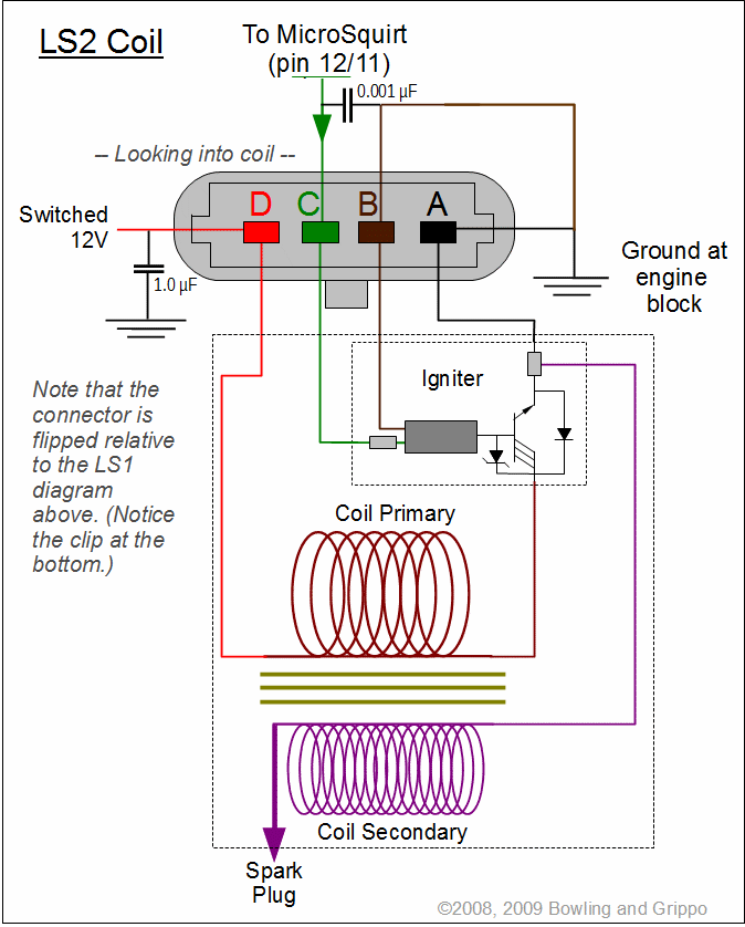
Coil On Plug Wiring Diagrams are essential tools for understanding the electrical system in modern vehicles. These diagrams provide a detailed illustration of how the ignition coils are connected to the engine’s control module and other components. By studying the Coil On Plug Wiring Diagram, mechanics can troubleshoot electrical issues, diagnose problems, and perform proper maintenance on the vehicle.
Why are Coil On Plug Wiring Diagrams essential?
- Help in diagnosing and troubleshooting electrical issues
- Provide a clear visual representation of the ignition coil wiring
- Aid in understanding the interaction between the ignition coils and other components
Reading and interpreting Coil On Plug Wiring Diagrams
When reading a Coil On Plug Wiring Diagram, it is important to pay attention to the color codes, symbols, and connections. Each wire is color-coded to indicate its function, such as power supply, ground, or signal. Understanding these color codes is crucial for interpreting the diagram correctly.
Using Coil On Plug Wiring Diagrams for troubleshooting
- Identify faulty connections or damaged wires
- Check for continuity and proper voltage levels
- Verify the correct sequence of connections between components
Safety precautions when working with wiring diagrams
When working with electrical systems and using Coil On Plug Wiring Diagrams, it is important to follow these safety tips:
- Always disconnect the battery before working on the electrical system
- Use insulated tools to prevent electrical shock
- Avoid working on the wiring when the engine is running
- Double-check all connections before reassembling the components
Coil On Plug Wiring Diagram
Coil-on-plug wiring and install with pics | DSMtuners
Tech Crew: Audi Coil Pack Wiring Diagram

Coil-On-Plug Conversions

Ls1 Coil Pack Wiring Diagram – Wiring Diagram

Coil On Plug , COP Wiring for all years in 1 Thread ! | DSMtuners.com
Coil-on-plug wiring and install with pics | DSMtuners
Gm Ignition Coil Wiring Diagram
