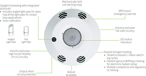
When it comes to understanding the wiring of a ceiling occupancy sensor, having a clear diagram can make all the difference. A Ceiling Occupancy Sensor Wiring Diagram provides a visual representation of the electrical connections and components involved in the installation of a ceiling occupancy sensor.
Importance of Ceiling Occupancy Sensor Wiring Diagram
Ceiling Occupancy Sensor Wiring Diagrams are essential for several reasons:
- Helps in understanding the electrical connections
- Ensures proper installation of the sensor
- Aids in troubleshooting electrical issues
- Provides a reference for future maintenance or upgrades
Reading and Interpreting Ceiling Occupancy Sensor Wiring Diagram
When reading a Ceiling Occupancy Sensor Wiring Diagram, it’s important to pay attention to the following:
- Color coding of wires
- Connection points for each component
- Electrical symbols used in the diagram
Using Ceiling Occupancy Sensor Wiring Diagram for Troubleshooting
Ceiling Occupancy Sensor Wiring Diagrams can be invaluable when troubleshooting electrical problems. By following the diagram, you can identify faulty connections, damaged wires, or incorrect installations that may be causing issues with the sensor.
It’s important to follow these steps:
- Identify the specific issue with the sensor
- Refer to the wiring diagram to locate the relevant components
- Check for continuity, voltage, and proper connections
- Make necessary repairs or replacements as needed
Safety Tips for Working with Ceiling Occupancy Sensor Wiring Diagram
When working with electrical systems and using wiring diagrams, it’s crucial to prioritize safety. Here are some safety tips and best practices to keep in mind:
- Always turn off the power supply before working on any electrical components
- Use insulated tools to prevent electrical shocks
- Double-check all connections before turning the power back on
- Wear appropriate safety gear, such as gloves and goggles
- If you’re unsure about any step, consult a professional electrician
Ceiling Occupancy Sensor Wiring Diagram
How to Wire a Ceiling Occupancy Sensor: A Step-By-Step Wiring Diagram Guide

How to Wire a Ceiling Occupancy Sensor: A Step-By-Step Wiring Diagram Guide

[DIAGRAM] Lutron Occupancy Sensor Wiring Diagram And Instructions
![Ceiling Occupancy Sensor Wiring Diagram [DIAGRAM] Lutron Occupancy Sensor Wiring Diagram And Instructions](http://aleccontrol.com/images/alecWiring2.jpg)
CDT-05-180-R Dual Technology Ceiling Low Voltage Occupancy Sensor

Ceiling Occupancy Sensor Wiring Diagram General Wirin – vrogue.co

Rayzeek PIR Motion Detector Ceiling Mount Occupancy Sensor

Leviton ODC Multi-Tech Ceiling Occupancy Sensor

Ceiling Mount Occupancy Sensor Wiring Diagram | Shelly Lighting
