Introduction
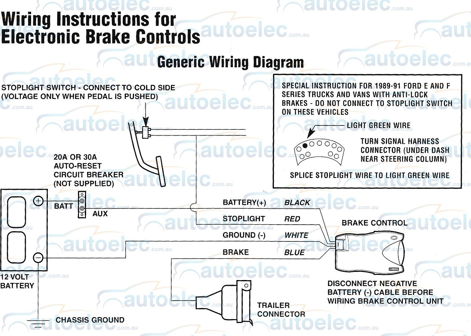
Brake Controller Wiring Diagram is a crucial tool for any mechanic or DIY enthusiast working on brake systems. These diagrams provide a visual representation of the electrical connections within a brake controller system, helping individuals understand how various components are wired together.
Importance of Brake Controller Wiring Diagram
Brake Controller Wiring Diagrams are essential for the following reasons:
- Ensure proper installation of brake controllers
- Help in troubleshooting electrical issues
- Guide in understanding the wiring connections
Reading and Interpreting Brake Controller Wiring Diagram
When interpreting a Brake Controller Wiring Diagram, consider the following:
- Identify the components and their corresponding symbols
- Follow the wiring paths to understand the connections
- Pay attention to color codes and labels for clarity
Using Brake Controller Wiring Diagram for Troubleshooting
Brake Controller Wiring Diagrams are invaluable for troubleshooting electrical problems. By following the wiring diagram, you can:
- Locate potential faulty connections or components
- Check for continuity and voltage at specific points
- Verify proper grounding and wiring integrity
Safety Tips for Working with Brake Controller Wiring Diagram
When working with electrical systems and using wiring diagrams, it is essential to prioritize safety. Follow these safety tips:
- Always disconnect the power source before working on the wiring
- Use insulated tools to prevent electrical shocks
- Avoid working in wet or damp conditions
- Double-check all connections before powering up the system
Brake Controller Wiring Diagram
How To Install the Circuit Breakers From Brake Controller Installation

Wiring Diagram Brake Controller – Home Wiring Diagram

Reese Pod Brake Controller Wiring Diagram – paceinspire

Electric Brake Controller Wiring Schematic

Hopkins Agility Brake Controller Wiring Diagram For 2007 Dodge Ram 1500

Tekonsha Brake Controller Wiring Diagram – General Wiring Diagram

Curt Brake Controller Wiring Diagram – inspiresio

Ford F250 Trailer Brake Controller Wiring Diagram: Q&A Guide | JustAnswer
